Scanning in angle-resolved reflectometry and algorithmically eliminating diffraction from optical metrology

a technology of angle-resolved reflectometry and optical metrology, applied in semiconductor/solid-state device testing/measurement, instruments, material analysis, etc., can solve the problems of diffraction, the feature of a test pattern is not uniform, and the application of angle-resolved reflectometry becomes ever more challenging

Active Publication Date: 2015-04-30
KLA TENCOR TECH CORP
View PDF17 Cites 10 Cited by
  • Summary
  • Abstract
  • Description
  • Claims
  • Application Information

AI Technical Summary

Benefits of technology

The present invention provides an angle-resolved reflectometer and a method for estimating the size of an aperture in a metrology system and compensating for the diffraction error caused by the size of the aperture. This innovation allows for more accurate and precise measurements to be made.

Problems solved by technology

As target sizes become smaller, due to cost and production constraints, applying angle-resolved reflectometry is becoming evermore challenging.
The features that make up a test pattern are not uniform throughout the entire test pattern.
They invariably contain imperfections such as edge roughness, variable line width and side wall slope inconsistencies.
This, however, comes at the cost of diffractions.

Method used


Image

  • Scanning in angle-resolved reflectometry and algorithmically eliminating diffraction from optical metrology
  • Scanning in angle-resolved reflectometry and algorithmically eliminating diffraction from optical metrology
  • Scanning in angle-resolved reflectometry and algorithmically eliminating diffraction from optical metrology

Examples


Embodiment Construction

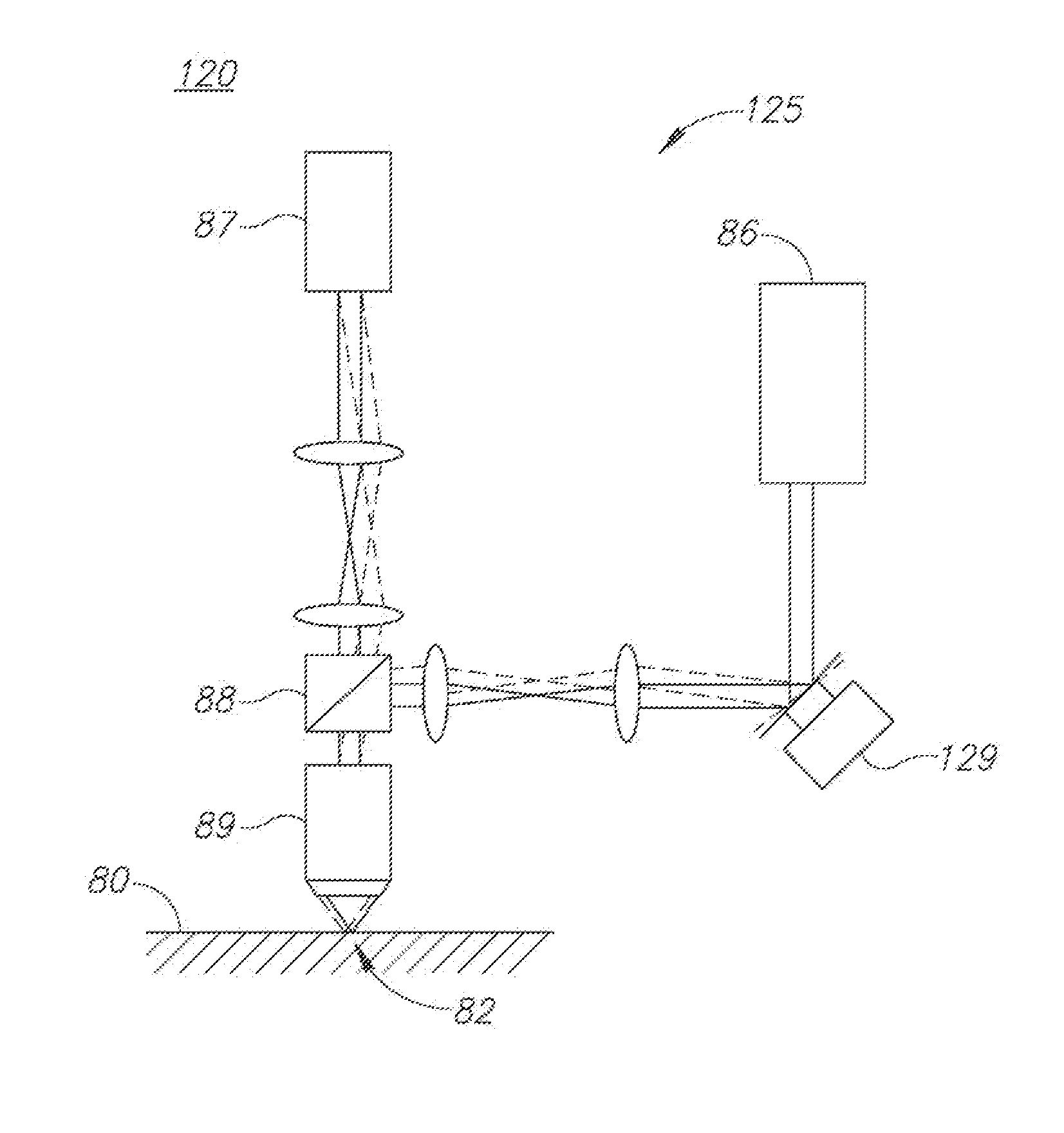
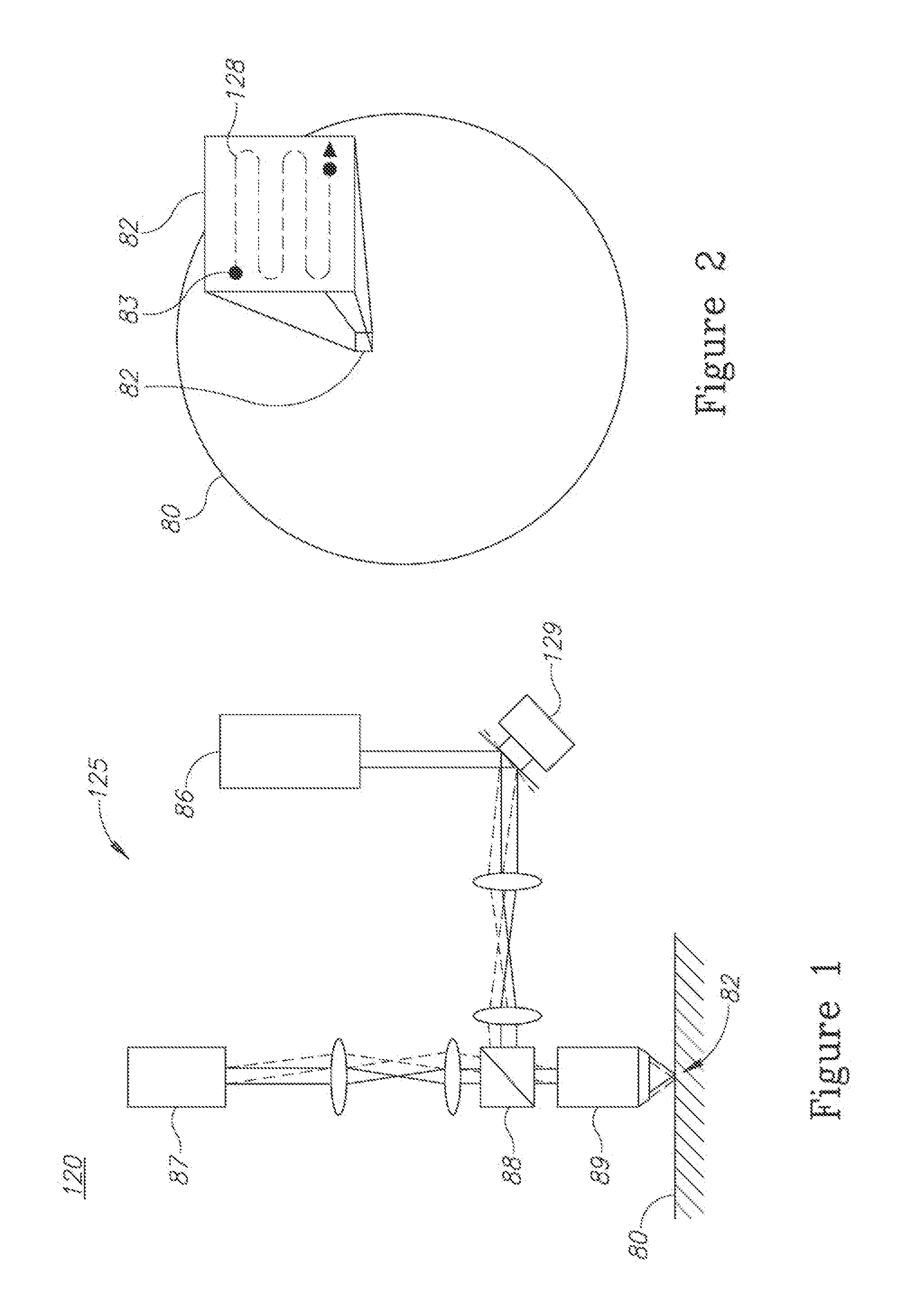
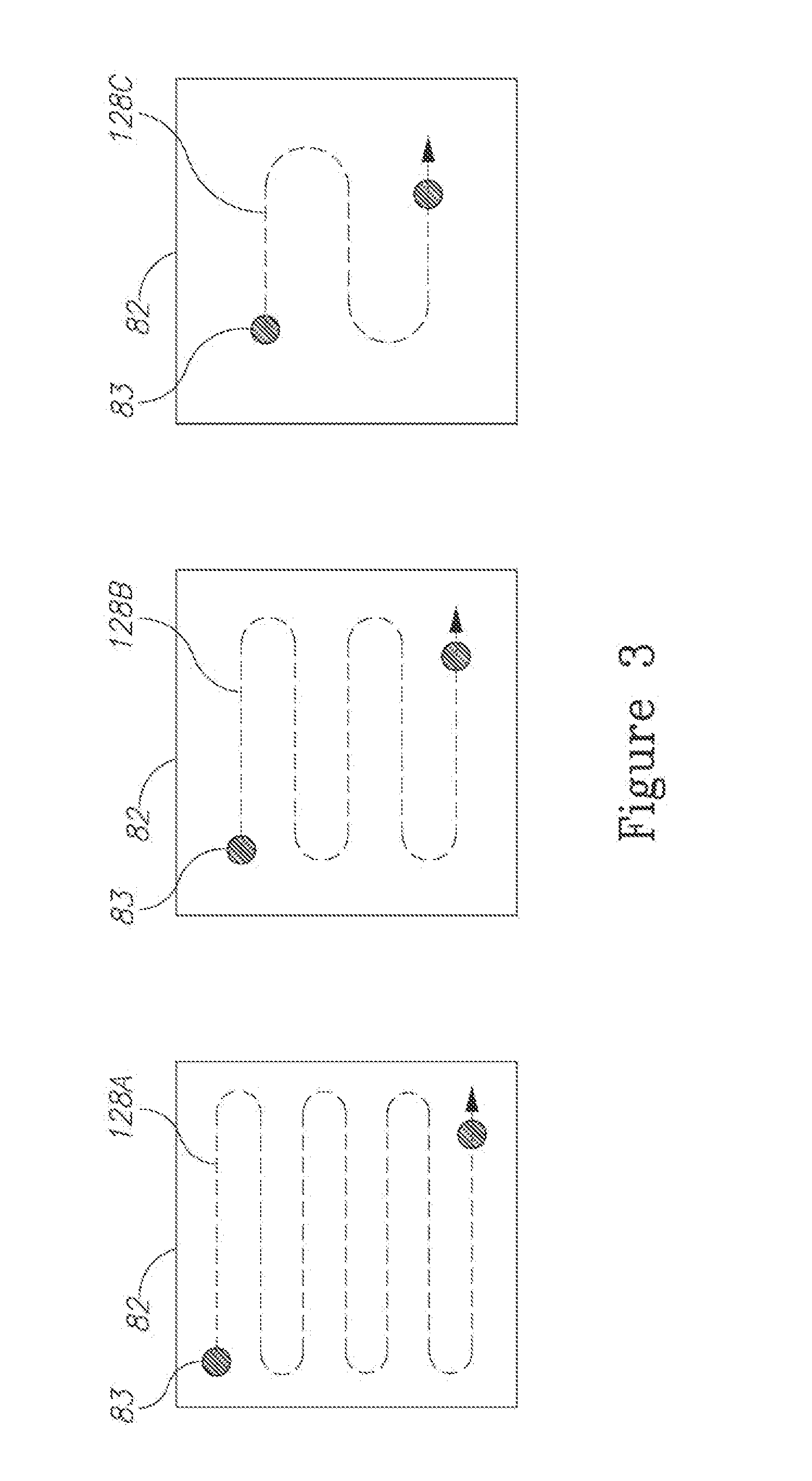
[0026]Prior to setting forth the detailed description, it may be helpful to set forth definitions of certain terms that will be used hereinafter.

[0027]The terms “target” or “metrology target” as used herein in this application refer to any structure that is used for metrology needs. Targets may be part of any layer in the lithographic process, and targets may include different structures on the same layer or on different layers.

[0028]The terms “speckle pattern” or “speckle” as used herein in this application refer to an intensity pattern of an optical signal that is produced by interference of at least two wavefronts, and generally to a source of measurement error resulting from interfering wavefronts at the sensor plane.

[0029]With specific reference now to the drawings in detail, it is stressed that the particulars shown are by way of example and for purposes of illustrative discussion of the preferred embodiments of the present invention only, and are presented in the cause of pro...


PUM

PropertyMeasurementUnit
angle-aaaaaaaaaa
mechanicalaaaaaaaaaa
optical scanningaaaaaaaaaa

Abstract

Angle-resolved reflectometers and reflectometry methods are provided, which comprise a coherent light source, an optical system arranged to scan a test pattern using a spot of coherent light from the light source to yield realizations of the light distribution in the collected pupil, wherein the spot covers a part of the test pattern and the scanning is carried out optically or mechanically according to a scanning pattern, and a processing unit arranged to generate a composite image of the collected pupil distribution by combining the pupil images. Metrology systems and methods are provided, which reduce diffraction errors by estimating, quantitatively, a functional dependency of measurement parameters on aperture sizes and deriving, from identified diffraction components of the functional dependency which relate to the aperture sizes, correction terms for the measurement parameters with respect to the measurement conditions.

Description

CROSS REFERENCE TO RELATED APPLICATIONS[0001]This application is filed under 35 U.S.C. §120 and §365(c) as a continuation of International Patent Application Serial No. PCT / US13 / 47691, filed on Jun. 25, 2013, which application claims the benefit under 35 U.S.C. 119(e) of U.S. Provisional Patent Application No. 61 / 664,477, filed on Jun. 26, 2012 and U.S. Provisional Patent Application No. 61 / 764,435, filed on Feb. 13, 2013, which applications are incorporated herein by reference in their entirety.FIELD OF THE INVENTION[0002]The present invention relates to the field of metrology in semiconductor devices and angle-resolved reflectometry, and more particularly, to removal of aperture diffraction effects and to enhancing accuracy and reducing noise in angle-resolved reflectometry.BACKGROUND OF THE INVENTION[0003]Angle-resolved reflectometry is a technique that is used for measuring parameters such as overlay and critical dimension on a test pattern that is printed on a wafer. A cone of ...

Claims


Application Information

Patent Timeline
Patent Type & Authority Applications(United States)
IPC IPC(8): G01N21/55G01B11/00
CPCG01N21/55G01N2201/06113G01B11/00G01N21/9501G01N21/956G01N2201/104G01B9/02H01L22/12
Inventor MANASSEN, AMNONHILL, ANDREWKANDEL, DANIELSELA, ILANBACHAR, OHADBRINGOLTZ, BARAK
Owner KLA TENCOR TECH CORP
Why Eureka
Try Eureka