Movement control device for vehicle

a technology of moving control and vehicle, which is applied in the direction of process and machine control, battery/fuel cell control arrangement, instruments, etc., can solve the problems of improper complexity or increase of the device, difficulty in a conventional device to perform deceleration control, and vehicle may continue its turning improperly

Active Publication Date: 2015-04-30
MAZDA MOTOR CORP
View PDF15 Cites 15 Cited by
  • Summary
  • Abstract
  • Description
  • Claims
  • Application Information

AI Technical Summary

Benefits of technology

[0008]The present invention has been devised in view of the above-described matters, and an object of the present invention is to provide a movement control device for a vehicle which can prevent a delay of the yaw rate's convergence even when the turn-back steering is conducted, thereby controlling the vehicle's movement properly so that the driver's operation during the vehicle's cornering can be natural and stable.
[0010]According to the present invention, since the amount of drive-force decreasing is increased quickly as the yaw-rate relating quantity increases after starting of the vehicle's steering in a state in which the turn-back steering is not conducted (in an initial stage of the lane change before the turn-back steering, for example), the vehicle can have the declaration quickly at the start timing of the steering of the vehicle, so that the sufficient load can be made to quickly act on the front wheels as the steered wheels. Consequently, the friction between the front wheels as the steered wheels and the road surface increases and thereby the cornering force increases, so that the turning performance of the vehicle at the initial timing of the vehicle's cornering can be improved and thereby the responsiveness to the turning operation of the steering can be improved. Further, since it is configured such that the increasing rate of the amount of the above-described drive-force decreasing becomes smaller according to the increase of the yaw-rate relating quantity, it can be prevented that the deceleration of the vehicle during the vehicle's cornering becomes excessive (too large), so that the deceleration can be decreased quickly when the steering is finished. Accordingly, the driver can be prevented from having improper dragging feelings of decreasing of the drive force when the vehicle gets out of the cornering. Additionally, since the drive force is increased in a state in which the turn-back steering is conducted and the absolute value of the steering angle of the vehicle decreases (when the driver returns the steering wheel to its central position in a late stage of lane changing, for example), the vehicle can have acceleration at the steering for returning to the vehicle's turning ahead, so that the load acting on rear wheels can be increased. Consequently, the cornering force of the rear wheels increases, so that the straight advancing ability of the vehicle can be improved and thereby the yaw rate can be surely made to converge. Thus, the movement control device for a vehicle according to the present invention can prevent the delay of the yaw rate's convergence even when the turn-back steering is conducted, thereby controlling the vehicle's movement properly so that the driver's operation during the vehicle's cornering can be natural and stable.
[0011]According to an embodiment of the present invention, the above-described decreasing control of the drive force of the vehicle is performed in a case in which the absolute value of the steering angle of the vehicle increases. Thereby, since the drive fore of the vehicle is decreased in the case in which the absolute value of the steering angle of the vehicle increases because of the turning operation of the steering, the sufficient load can be made to quickly act on the front wheels as the steered wheels when the turning operation of the steering is conducted, so that the responsiveness of the vehicle to the turning operation of the steering can be improved surely.
[0012]According to another embodiment of the present invention, the vehicle is an electric-drive vehicle equipped with a motor to drive wheels and a battery to supply electric power to the motor and store regenerative electric power generated by the motor, and the decreasing control of the drive force of the vehicle is performed by controlling the amount of the regenerative electric power generated by the motor. Thereby, the drive force of the vehicle can be decreased directly by decreasing a torque of the motor. Accordingly, compared with a case in which the drive force of the vehicle is decreased by controlling an oil-pressure brake unit, the responsiveness of the drive-force decreasing can be improved, so that the movement of the vehicle can be controlled more directly.
[0013]According to another embodiment of the present invention, the vehicle is further equipped with a battery-state detector to detect a state of the battery and an indicator to indicate information relating to the drive force's control, and the controlling of the drive force of the vehicle further includes a control of not decreasing the drive force of the vehicle and making the indicator indicate the information that the drive force of the vehicle is not decreased when it is determined based on the battery state detected by the battery-state detector that the battery is incapable of storing the regenerative electric power generated by the motor. Thereby, since the torque of the motor is not decreased so that the regenerative electric power is not generated in a case in which the battery is overcharged because of the storing of the regenerative electric power generated by the motor or a case in which the battery temperature exceeds an allowable temperature range, the battery can be prevented from having any damage caused by the overcharging or the deviation from the allowable temperature range. Further, since the indicator indicates the information that the drive force of the vehicle is not decreased, the driver can be prevented from having uncomfortable feelings because the drive force is not decreased when the vehicle gets into the cornering.

Problems solved by technology

Accordingly, it may be difficult for a conventional device to perform the deceleration control of the vehicle at an appropriate timing.
Herein, the vehicle movement control device of the above-described patent document predicts a corner (curve) located in front of the traveling vehicle by using a camera and starts the control of the oil-pressure brake system before reaching the corner in order to solve the above-described difficulty, but this method may cause improper complexity of the device or costs increase.
However, if the driver's steering operation fails to follow the speed of the vehicle's yaw rate increasing, there is a concern that the yaw rate of the vehicle may not converge to zero (0) even at the timing when the vehicle turns ahead, so that the vehicle may continue its turning improperly.

Method used


Image

  • Movement control device for vehicle
  • Movement control device for vehicle
  • Movement control device for vehicle

Examples


Embodiment Construction

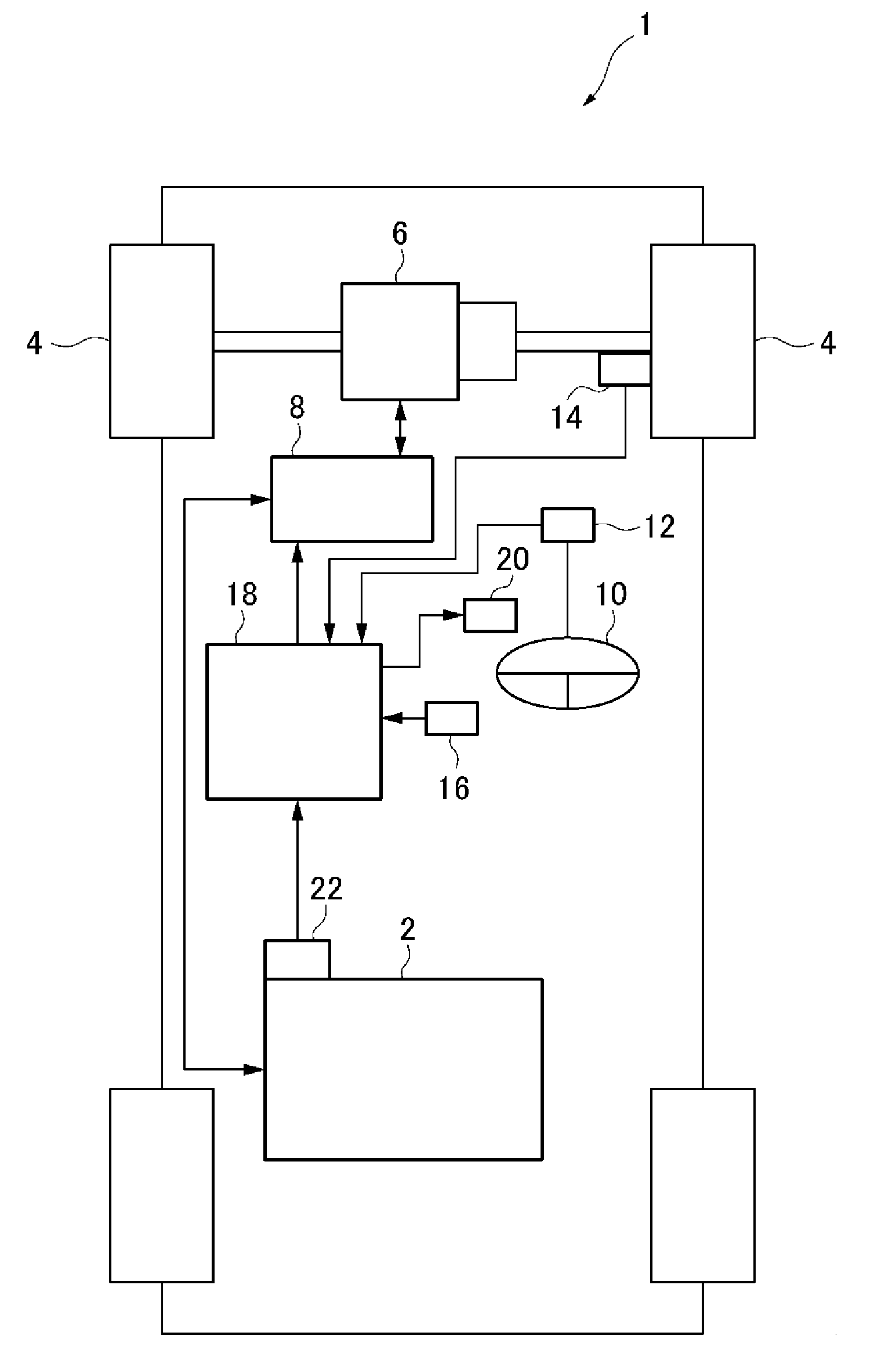
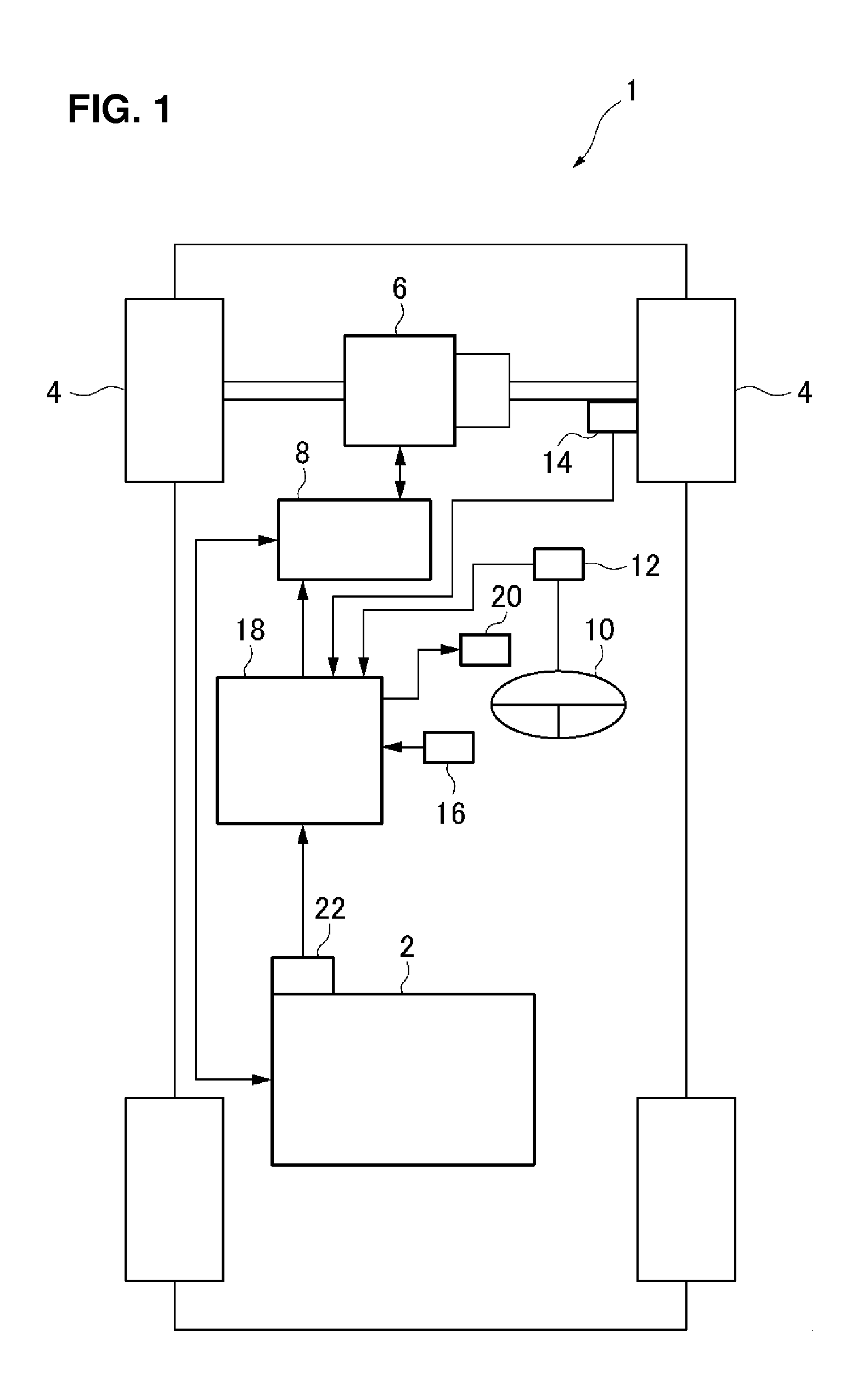
[0023]Hereinafter, a movement control device for a vehicle according to an embodiment of the present invention will be described referring to the accompanying drawings. First, a vehicle installing the movement control device for a vehicle according to the embodiment of the present invention will be described referring to FIG. 1. FIG. 1 is a block diagram showing entire constitution of the vehicle installing the movement control device for a vehicle according to the embodiment of the present invention.

[0024]As shown in FIG. 1, the vehicle 1 installing the movement control device for a vehicle according to the present embodiment installs a battery 2 (chargeable battery) as a power source, and is an electric automotive vehicle or a hybrid automotive vehicle which is equipped with front wheels steered. A motor 6 to drive driving wheels 4 (right-and-left front wheels in an example of FIG. 1) is installed at a vehicle-body front portion of the vehicle 1. Further, an inverter 8 is arranged...


PUM


Abstract

A movement control device for a vehicle comprises a yaw-acceleration calculation portion to calculate a target yaw acceleration of the vehicle, a turn-back steering determination portion to determine whether a turn-back steering of the vehicle is conducted or not, and a drive-force control portion to a drive force of the vehicle. The control of the drive-force control portion is configured such that when the turn-back steering is not conducted, the amount of drive-force decreasing is increased with a specified increasing rate as the target yaw acceleration increases, the specified increasing rate becoming smaller as the target yaw acceleration increases, and when the turn-back steering is conducted, the drive force is increased in a case in which an absolute value of a steering angle of the vehicle decreases.

Description

BACKGROUND OF THE INVENTION[0001]The present invention relates to a movement control device for a vehicle, and in particular, relates to the movement control device for a vehicle which controls a movement of the vehicle equipped with front wheels steered.[0002]Conventionally, a control device capable of controlling a movement of a vehicle so as to become stable when the vehicle's movement is unstable because of a slip or the like (such as an anti-sideslip apparatus) is known. Specifically, a control device, in which when it is detected that under-steering or over-steering movements happen to the vehicle during vehicle's cornering or the like, the speed of wheels are decelerated properly to restraint such movements, is known.[0003]Meanwhile, another type of control device to adjust a load acting on the front wheels as the steered wheels (see US Patent Application Publication No. 2012 / 0209489 A1, for example) is known. This control device is different from the above-described control ...

Claims


Application Information

Patent Timeline
Patent Type & Authority Applications(United States)
IPC IPC(8): B60L11/18B60W40/114
CPCB60L11/1861B60L11/18B60W40/114B60L7/14B60L15/2009B60L2240/22B60L2240/24B60L2240/423B60L2240/545B60L2240/547B60L2240/549B60L2250/16B60W10/184B60W10/26B60W30/045B60W30/18127B60W2510/244B60W2520/14B60W2540/18B60W2710/083B60L58/12B60L58/25Y02T10/64Y02T10/70Y02T10/72
Inventor NOBUMOTO, HIDETOSHISUNAHARA, OSAMUYAMASHITA, SHINICHIRO
Owner MAZDA MOTOR CORP
Why Eureka
Try Eureka