Heat generating device

a heat generation device and heat generation technology, applied in the field of heat generation devices, can solve problems such as burning of occupants

Inactive Publication Date: 2015-05-07
DENSO CORP
View PDF3 Cites 2 Cited by
  • Summary
  • Abstract
  • Description
  • Claims
  • Application Information

AI Technical Summary

Benefits of technology

[0007]With the above arrangements, the parallel connection of the at least two of the heating resistors results in a decrease in heat mass of each of the heating resistors. The arrangement of the heating resistors at an interval away from each other in the insulating base containing a thermoplastic resin serves to avoid the transfer of heat in a planar direction, thus minimizing the application of a large amount of heat to limbs of a person through a contact with the heat generating device.

Problems solved by technology

The limbs of the occupant may contact the heat generating device, thus resulting in application of a great deal of heat to the occupant through the contact, which may cause the occupant to be burned in the case where the heat mass of the heating resistors is great.

Method used


Image

  • Heat generating device
  • Heat generating device
  • Heat generating device

Examples


first embodiment

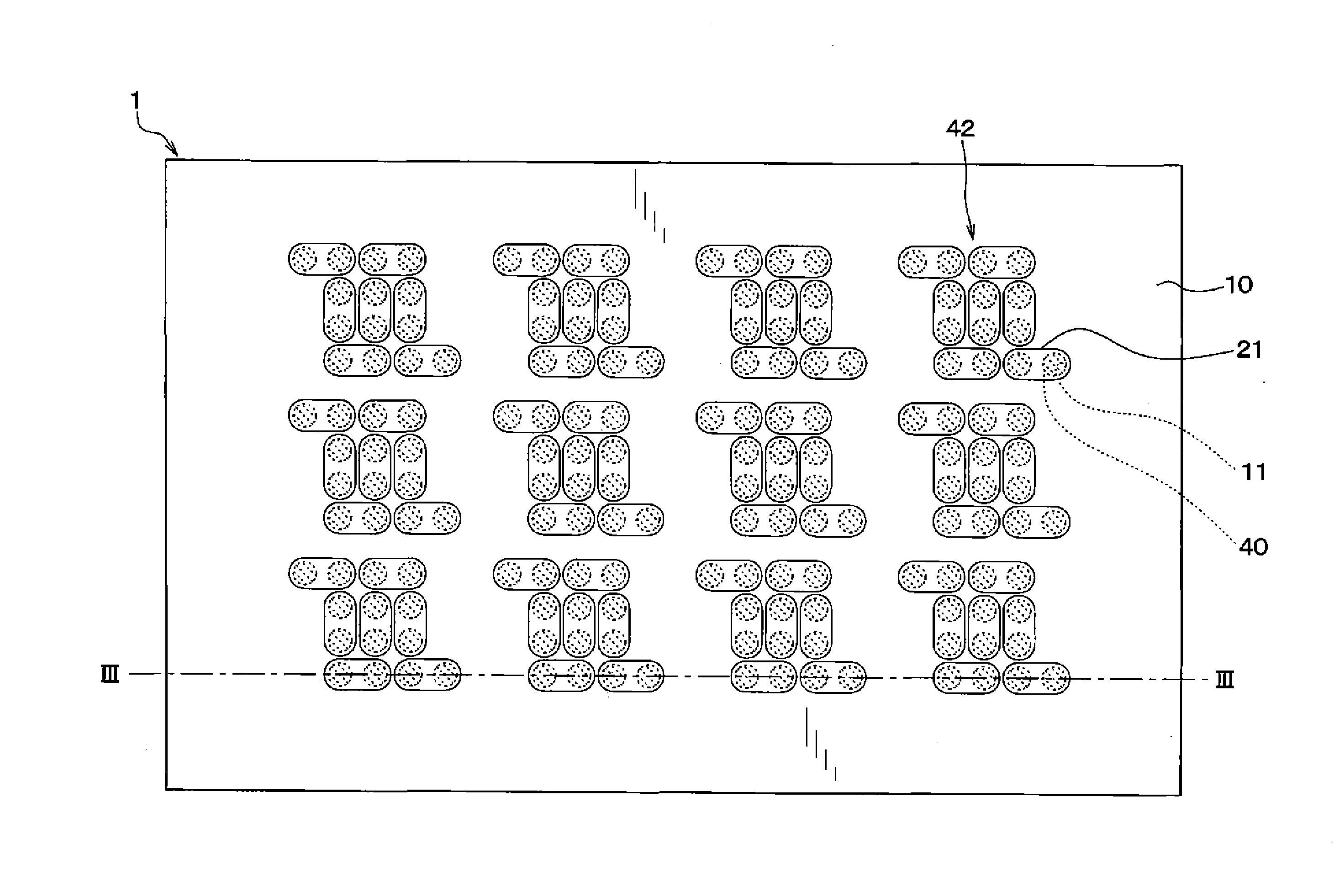
[0019]The first embodiment of the invention will be described below with reference to drawings. The heat generating device 1 of this embodiment is, as illustrated in FIGS. 1 to 3, made by unifying an insulating base 10, a front side protective member 20, and a reverse side protective layer 30 and arranging heating resistors 40 inside that unit.

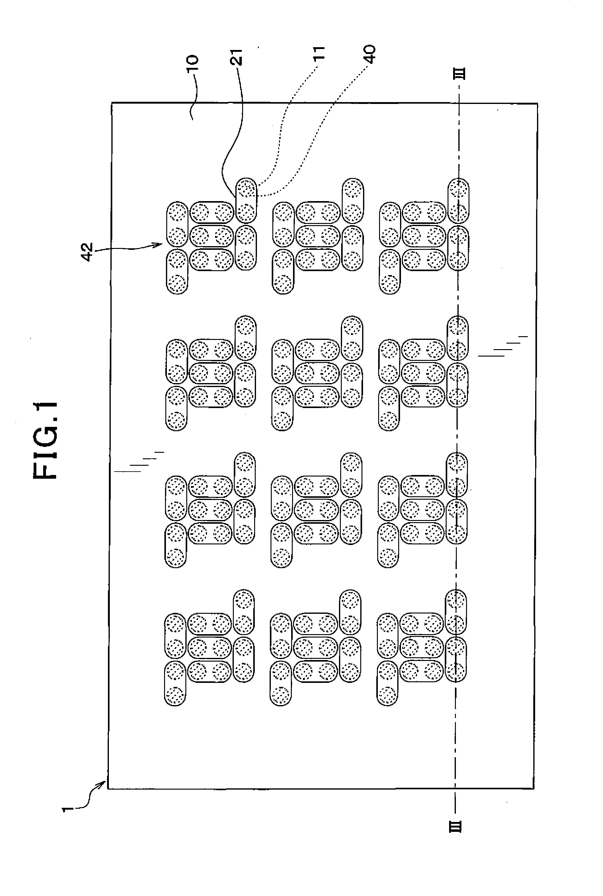
[0020]FIG. 1 omits the front side protective member 20 for the ease of understanding. FIG. 2 omits the reverse side protective member 20 for the ease of understanding. FIGS. 1 and 2 are not sectional views, but hatch the heating resistors 40.

[0021]In this embodiment, the insulating base 10 is formed by a rectangular planar thermoplastic resin film containing polyether ether ketone (PEEK) and polyetherimide (PEI). The insulating base 10 has a plurality of via holes 11 extending through a thickness thereof.

[0022]The insulating base 10 has the 168 via holes 11 which are broken down into a plurality of groups each made up of fourteen of the via ho...

second embodiment

[0046]The heat generating device 1 according to the second embodiment of the invention will be described below. The heat generating device 1 of this embodiment is different from the one of the first embodiment in that all the heating resistors 40 are connected in parallel. Other arrangements are identical, and explanation thereof in detail will be omitted here.

[0047]The front side protective member 20, as illustrated in FIGS. 7 to 9, has a single front side layer 21 formed on the surface 20a facing the insulating base 10. The front side layer 21 is electrically connected to all the healing resistors 40. In other words, the respective heating resistors 40 are electrically coupled with the same front side layer 21.

[0048]For the sake of ease of understanding, FIG. 7 omits the front side protective member 20. FIG. 7 is not a sectional view, but hatches the heating resistors 40. On the front side protective member 20, a layer-to-layer connecting member, not shown, is formed which is elec...


PUM

PropertyMeasurementUnit
thicknessaaaaaaaaaa
conductiveaaaaaaaaaa
temperatureaaaaaaaaaa

Abstract

To provide a heat generating device which is capable of minimizing the application of a large amount of heat through a contact with the heat generating device. The heat generating device includes an insulating base which contains a thermoplastic resin and has a front surface and a reverse surface and in which a plurality of via holes are formed to extend through a thickness, and heating resistors which are disposed in the via holes and generated heat when energized. Some of the heating resistors are connected in parallel.

Description

TECHNICAL FIELD[0001]The invention relates to a heat generating device equipped with heating resistors which generate heat when energized.BACKGROUND ART[0002]For instance, Japanese Patent First Publication No. 9-63755 proposes a heat generating device equipped with a plurality of heating resistors between two rubber sheets. Such a heat generating device works to generate heat by electrically energizing the heating resistors to heat surfaces of the rubber sheets to a given temperature and is used.[0003]However, the above heat generating device has the heating resistors made of a single piece of wire. In other words, a heating part is arranged continuously, thus resulting in an increase in heat mass (i.e., heat capacity).[0004]The above heat generating device is mounted on, for example, a lower surface of a steering column in a passenger compartment of a vehicle and used as a heater to warm feet of an occupant of the vehicle through radiation of heat. The limbs of the occupant may con...

Claims


Application Information

Patent Timeline
Patent Type & Authority Applications(United States)
IPC IPC(8): H05B3/12H05B3/26H05K3/00H05B3/18
CPCH05B3/12H05B3/18H05K3/0044H05K3/0064H05B3/267H05B2203/009H05B2203/022Y10T29/49083
Inventor TANIGUCHI, TOSHIHISASHIRAISHI, YOSHIHIKOSAKAIDA, ATUSIOKAMOTO, KEIJISAITOU, KEITA
Owner DENSO CORP
Why Eureka
Try Eureka