
Large scale metal forming

a metal forming and large-scale technology, applied in the field of metal forming, can solve problems such as significant shrinkage in the pla

Active Publication Date: 2015-05-07
ILLINOIS TOOL WORKS INC
View PDF7 Cites 17 Cited by
  • Summary
  • Abstract
  • Description
  • Claims
  • Application Information

AI Technical Summary

Benefits of technology

The patent describes a method for making large metal plate pieces by either hot or cold forming. Cold forming is usually done using a linear press or roller, while hot forming can be done using a press or a heat source moving along a predetermined line. The hot forming method involves heating the plate surface and then quickly cooling it, causing significant shrinkage. The patent describes a heated line forming system that uses induction coils to create a heated line on the metal surface, and a system to maintain a dry area around the heated line without allowing the coolant to splash into it.

Problems solved by technology

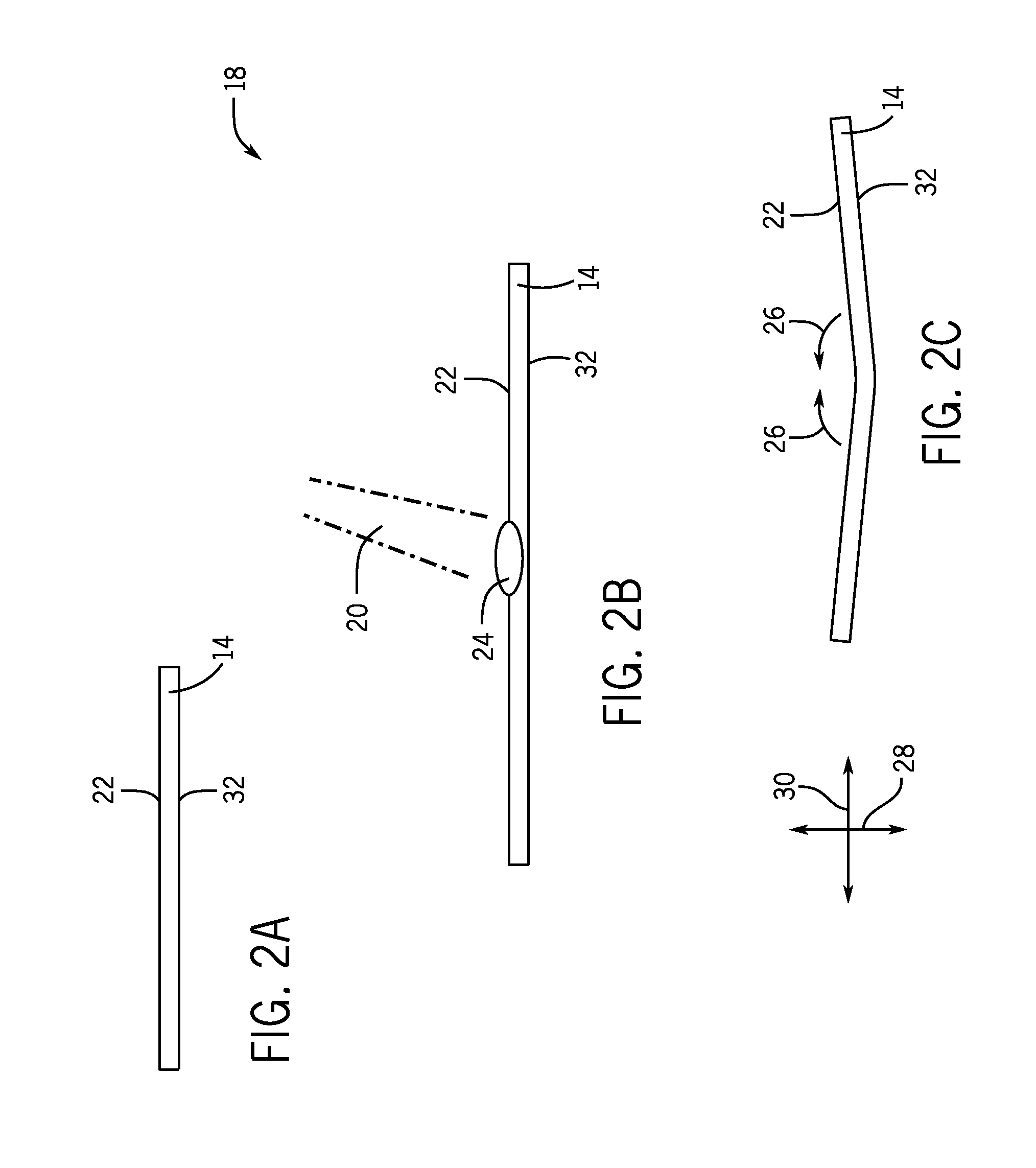
The use of through thickness heating and then cooling may cause significant shrinkage in-plate, a significant portion of which is in a direction perpendicular to the line of heating being traversed by the heat source or heated spot.

Method used


Image

  • Large scale metal forming
  • Large scale metal forming
  • Large scale metal forming

Examples


Embodiment Construction

[0018]One or more specific embodiments of the present invention will be described below. In an effort to provide a concise description of these embodiments, all features of an actual implementation may not be described in the specification. It should be appreciated that in the development of any such actual implementation, as in any engineering or design project, numerous implementation-specific decisions must be made to achieve the developers' specific goals, such as compliance with system-related and business-related constraints, which may vary from one implementation to another. Moreover, it should be appreciated that such a development effort might be complex and time consuming, but would nevertheless be a routine undertaking of design, fabrication, and manufacture for those of ordinary skill having the benefit of this disclosure.

[0019]When introducing elements of various embodiments of the present invention, the articles “a,”“an,”“the,” and “said” are intended to mean that ther...


PUM

PropertyMeasurementUnit
temperatureaaaaaaaaaa
induction poweraaaaaaaaaa

Abstract

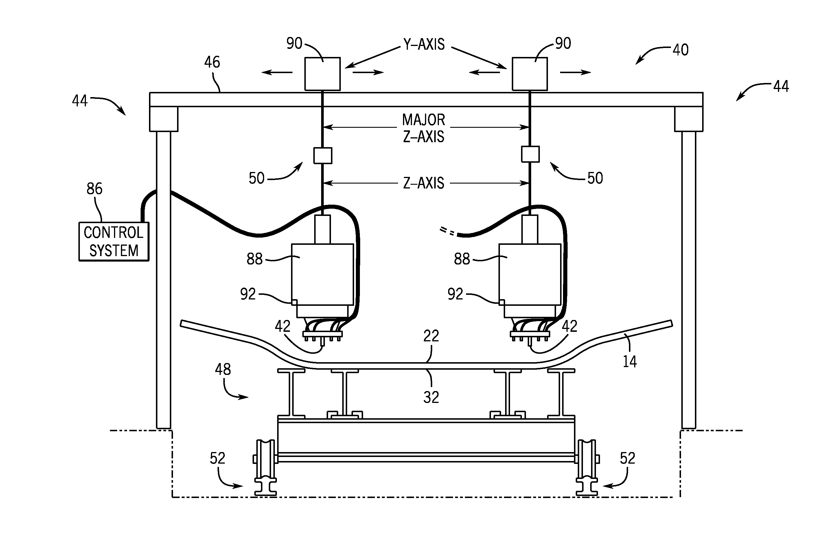
In certain embodiments described herein, a heated line forming system includes a heating coil system configured to produce a heated line on a surface of a metal part. The heated line forming system also includes an air knife cooling system configured to maintain a dry area for the heated line, and to direct a coolant (e.g., cooling water, liquified gases such as liquid argon, solidified gases such as carbon dioxide snow, and so forth) around the heated line via a spray mechanism such that the coolant does not flow or splash into the heated line on the metal part. In certain embodiments, the heated line forming system includes multiple induction coils arranged along a line and spaced a short distance apart, but which, when operated simultaneously together, form a heated line on a surface of a metal part.

Description

CROSS-REFERENCE TO RELATED APPLICATIONS[0001]This application claims priority from and the benefit of U.S. Provisional Application Ser. No. 61 / 901,294, entitled “LARGE SCALE METAL FORMING,” filed Nov. 7, 2013, which is hereby incorporated by reference in its entirety for all purposes.BACKGROUND[0002]The invention relates generally to metal forming, and more particularly, to automated thermal forming processes and systems.[0003]Steel and, to a lesser extent, aluminum are the structural materials of choice for most fabricating. Consequently, metal bending and metal forming operations will continue to be of significant importance to fabricators. As quality and productivity requirements increase, automated systems will be required to meet those demands. Today, the fabricating industry depends on manual processes, such as line heating, spot heating, mechanical bending, press brakes, and manually operated equipment for most metal forming operations. One major fabricating industry is the s...

Claims


Application Information

Patent Timeline
Patent Type & Authority Applications(United States)
IPC IPC(8): H05B6/42H05B6/44H05B6/10
CPCH05B6/42H05B6/44H05B6/103B21D11/20B21D37/16C21D2261/00C21D1/42C21D1/10Y02P10/25
Inventor JONES, JERALD EDWARDRHOADES, VALERIE LISACUNEO, ADAM N.
Owner ILLINOIS TOOL WORKS INC
Learn More