Power transmission system

Active Publication Date: 2015-05-07
SION ELECTRIC
View PDF14 Cites 9 Cited by
  • Summary
  • Abstract
  • Description
  • Claims
  • Application Information

AI Technical Summary

Benefits of technology

[0015]According to the present invention, the following can be achieved: effectively utilize even small amounts of power generated from few natural energy sources without waste when combining and transmitting groups of power generated from not only the commercial power source but also from natural energy sources (in power combination of a type utilizing a so-called power conditioner as mentioned above, weak power such as solar photovoltaic generation during cloudy weather was nearly unusable); utilize a plurality of power sources in combination; automatically supply power from another power source when one of the power sources is cut off; easily set a usage priority order for the plurality of power sources and select energy from a desired power source when utilize a plurality of power sources (for example, preferentially utilize the cheapest energy, compensate only an insufficient portion with the commercial power source, or preferentially utilize environmentally friendly energy); and utilize power without waste in compliance with various conditions depending on the type of

Problems solved by technology

In this method, the priority order of the power sources can be set by changing the voltage, but when a so-called backflow preve

Method used


Image

  • Power transmission system
  • Power transmission system
  • Power transmission system

Examples


Embodiment Construction

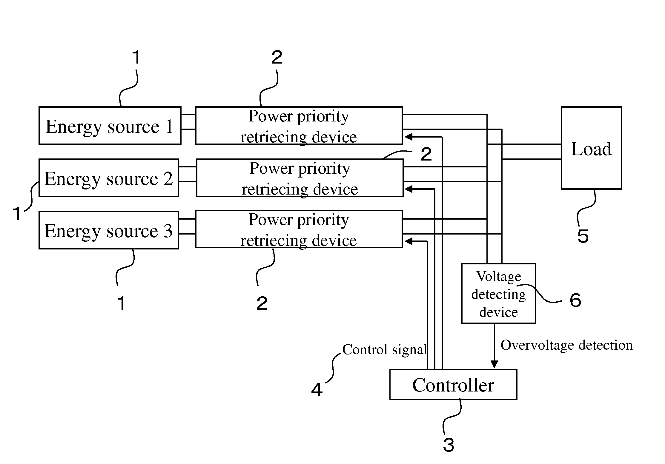
[0060]An embodiment of the present invention will now be explained below with reference to the drawings.

[0061]FIG. 1 is a configuration explanatory view explaining a schematic configuration of a power transmission system according to the present invention. In FIG. 1, each reference numeral 1 indicates an energy source. Herein, in this embodiment, an example is illustrated in which there are three energy sources 1 . . . , but the power transmission system can be configured as long as there is at least one energy source 1 . . . (if there is only one energy source 1, it is equivalent to a normal power source because it is not necessary to combine power sources).

[0062]Herein, the energy sources 1 represent various power generation devices, and particularly power generation devices utilizing natural energy (generators for solar photovoltaic generation, wind power generation, water power generation, and the like), but the energy sources 1 are not limited thereto. As long as it can be conv...


PUM


Abstract

A power transmission system, which has a plurality of DC power sources and a load that receives a supply of DC power, is characterized in that: a power priority retrieving device is attached to each DC power source; control is performed by a controller; and the amount of power to be delivered from a DC power source to which a power priority retrieving device is attached to the load is determined on the basis of the retrieved power priority.

Description

TECHNICAL FIELD[0001]The present invention relates to an device for power generation by natural energy and a device for controlling the supply of power generated by such a power generation device, and more specifically a power transmission system that varies the amount of power supplied from power sources consisting of a plurality of the power generation devices according to various set conditions and transmits it to a direct current (DC) load side.BACKGROUND ART[0002]Conventionally, a power source of power to be consumed is generally supplied only from an electric power company, and enough power is supplied such that it is not necessary to select a supply source.[0003]In other words, it has generally been recognized that the power from such an electric power company can meet the power demand for all consumers, and is sufficient enough that there are rarely any power outages.[0004]However, in recent years, due to earthquakes and other accidents, the dangers of relying on only a sing...

Claims


Application Information

Patent Timeline
IPC IPC(8): H02J1/14H02J1/10
CPCH02J1/10H02J1/14H02J1/12H02J1/102H02J1/106
Inventor MURANO, MINORUAKIBA, SUMINOBUTANAHASHI, SHIN
Owner SION ELECTRIC
Why Eureka
Try Eureka