Robot, controller, and robot system

a robot and controller technology, applied in the field of robots, can solve the problems of increasing the number of sensors in the robot arm with the reduction in size, reducing the price of sensors, and reducing the reliability of sensors, so as to achieve convenient change, improve convenience, and improve accuracy.

Inactive Publication Date: 2015-05-07
SEIKO EPSON CORP
View PDF4 Cites 17 Cited by
  • Summary
  • Abstract
  • Description
  • Claims
  • Application Information

AI Technical Summary

Benefits of technology

[0012]According to this configuration, the plurality of detection units and the first control unit are series-connected (so-called daisy chain connection) by the wiring unit, and thereby, compared to the case where the respective detection units and the first control unit are parallel-connected (so-called star connection), the number of wires may be significantly reduced. Further, signals may be sequentially transmitted (so-called serial transmission) between the plurality of detection units and the first control unit, and thereby, increase of the detection units may be addressed without increase in the number of wires. Furthermore, the number of wires may be reduced by use of the inertial sensor as the detection unit and daisy chain connection of the inertial sensor, and generation of vibration when the robot arm is damped may be suppressed using the inertial sensor. In addition, when the inertial sensor is daisy-chain-connected, it is not necessary to newly provide a terminal for connection of the inertial sensor, and addition in the number of inertial sensors is easier.
[0072]A robot system according to a eighth aspect of the invention includes the robot of the first aspect and a controller that controls the robot. The robot of the first aspect calculates the information of the position of the movable unit using a detection result of the angular velocity detection device, and thereby, the controller may control the position of the movable unit so that swing of the movable unit may be reduced or cancelled. As a result, the robot system of the third aspect may control the position of the movable unit with higher accuracy.

Problems solved by technology

Further, the number of sensors in the robot arm tends to increase with reduction in size, higher reliability, lower price of the sensors.
However, in the case where the sensors etc. are connected via parallel wiring as in Patent Document 1, a problem of increase in the number of wires arises.
In addition, it is necessary to add terminals for connection of the inertial sensors to a substrate (a relay board and a calculation unit) to which the inertial sensors are connected, and addition in the number of inertial sensors is difficult.

Method used


Image

  • Robot, controller, and robot system
  • Robot, controller, and robot system
  • Robot, controller, and robot system

Examples


first embodiment

Robot

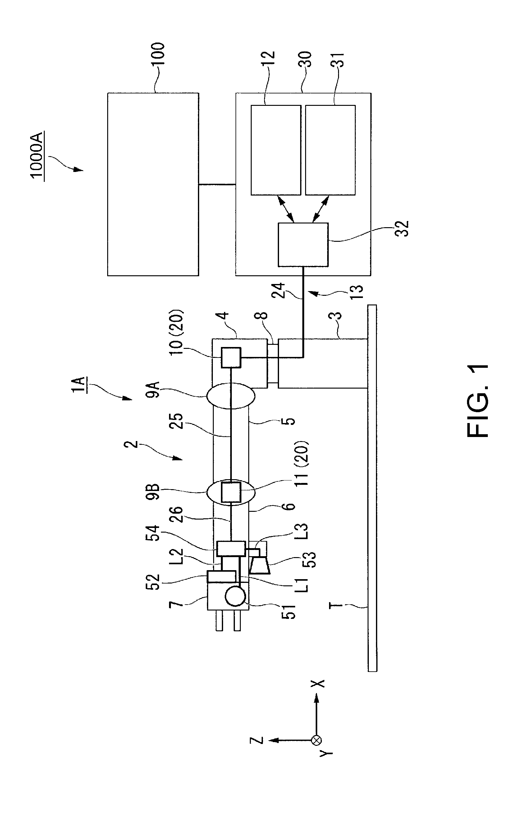
[0092]First, a robot 1A of the first embodiment will be explained with reference to FIG. 1.

[0093]FIG. 1 is a side view showing a schematic configuration of the robot 1A.

[0094]Further, in the following explanation, an XYZ orthogonal coordinate system is set and the positional relations among the respective members will be explained with reference to the XYZ orthogonal coordinate system. Specifically, lateral directions of the paper surface in FIG. 1 are referred to as X-axis directions, directions orthogonal to the paper surface in FIG. 1 are referred to as Y-axis directions, and vertical directions orthogonal to the paper surface in FIG. 1 are referred to as Z-axis directions. Further, directions around the X-axis, the Y-axis, and the Z-axis are referred to as a θX-direction, a θY-direction, and a θZ-direction, respectively.

[0095]The robot 1A is the so-called horizontal articulated robot (SCARA robot) including a robot arm 2 as shown in FIG. 1. The robot arm 2 has a base 3, a t...

second embodiment

Robot

[0119]Next, a robot 1B of the second embodiment will be explained with reference to FIG. 3.

[0120]FIG. 3 is a side view showing a schematic configuration of the robot 1B.

[0121]In the following explanation, the explanation of the parts equal to those of the robot 1A will be omitted and the same signs will be attached to the parts in the drawings.

[0122]As shown in FIG. 3, the robot 1B has a configuration in which a serial signal line 40 is used for the above described first signal line 24, second signal line 25, and third signal line 26. Further, in the hand unit 7, a force sensor (force detector) 55 and tactile sensors (detection unit) 56 are provided as end effectors in place of the illumination device and the imaging device 53, and connected to the sub-controller 54 via the respective wires L1 to L3. The rest of the configuration is basically the same as that of the above described robot 1A.

[0123]In the case of using the serial signal line 40, the detection signals detected by ...

third embodiment

Robot

[0125]Next, a robot 1C of the third embodiment will be explained with reference to FIG. 4.

[0126]FIG. 4 is a side view showing a schematic configuration of the robot 1C.

[0127]In the following explanation, the explanation of the parts equal to those of the robot 1A will be omitted and the same signs will be attached to the parts in the drawings.

[0128]As shown in FIG. 4, the robot 1C has a configuration in which another sub-controller (second control unit) 57 is added to the configuration of the robot 1B shown in FIG. 3. The sub-controller 57 is connected to the tactile sensors 56 via the wires L3, and connected to the sub-controller 54 via a wire L4. The rest of the configuration is basically the same as those of the above described robots 1A, 1B.

[0129]In the robot 1C of the embodiment, even when the numbers of sensors (detection units) and sub-controllers (second control units) increase, the number of signal lines (wires) may be significantly reduced by daisy chain connection us...


PUM


Abstract

A robot includes a robot arm, a drive unit that drives the robot arm, a first control unit that controls drive of the drive unit, a plurality of detection units at least one of which is an angular velocity sensor as an inertial sensor, and a wiring unit that series-connects the plurality of detection units and the first control unit.

Description

BACKGROUND[0001]1. Technical Field[0002]The present invention relates to a robot, a controller, and a robot system.[0003]2. Related Art[0004]For example, as industrial robots, horizontal articulated robots (SCARA robots), vertical articulated robots, etc. including robot arms have been used in related art. For control of the robots, information by sensors in the robot arms is used.[0005]In the robots in related art, the number of sensors has been smaller and the sensors have been limited to angle sensors. On the other hand, in recent multifunctional robots, for example, impedance control, damping control using inertial sensors such as angular velocity sensors (gyro sensors) etc. are performed. Further, the number of sensors in the robot arm tends to increase with reduction in size, higher reliability, lower price of the sensors. Furthermore, the number of wires in the robot arm tends to increase by communication with the inertial sensors, end effectors (hand units), etc.[0006]For wi...

Claims


Application Information

Patent Timeline
Patent Type & Authority Applications(United States)
IPC IPC(8): B25J9/16B25J15/00
CPCB25J9/1602Y10S901/09B25J15/00B25J9/1682B25J19/04B25J9/1674B25J13/088B25J19/0029
Inventor YAMAZAKI, TAKEMAIIDA, IZUMISAWADA, MUNENORISATO, DAISUKESEJIMO, ISAMUSASAI, SHIGENORI
Owner SEIKO EPSON CORP
Why Eureka
Try Eureka