

Cable lacing tie devices and methods of using the same
- Summary
- Abstract
- Description
- Claims
- Application Information
AI Technical Summary
Benefits of technology
Problems solved by technology
Method used
Image

Examples
Embodiment Construction
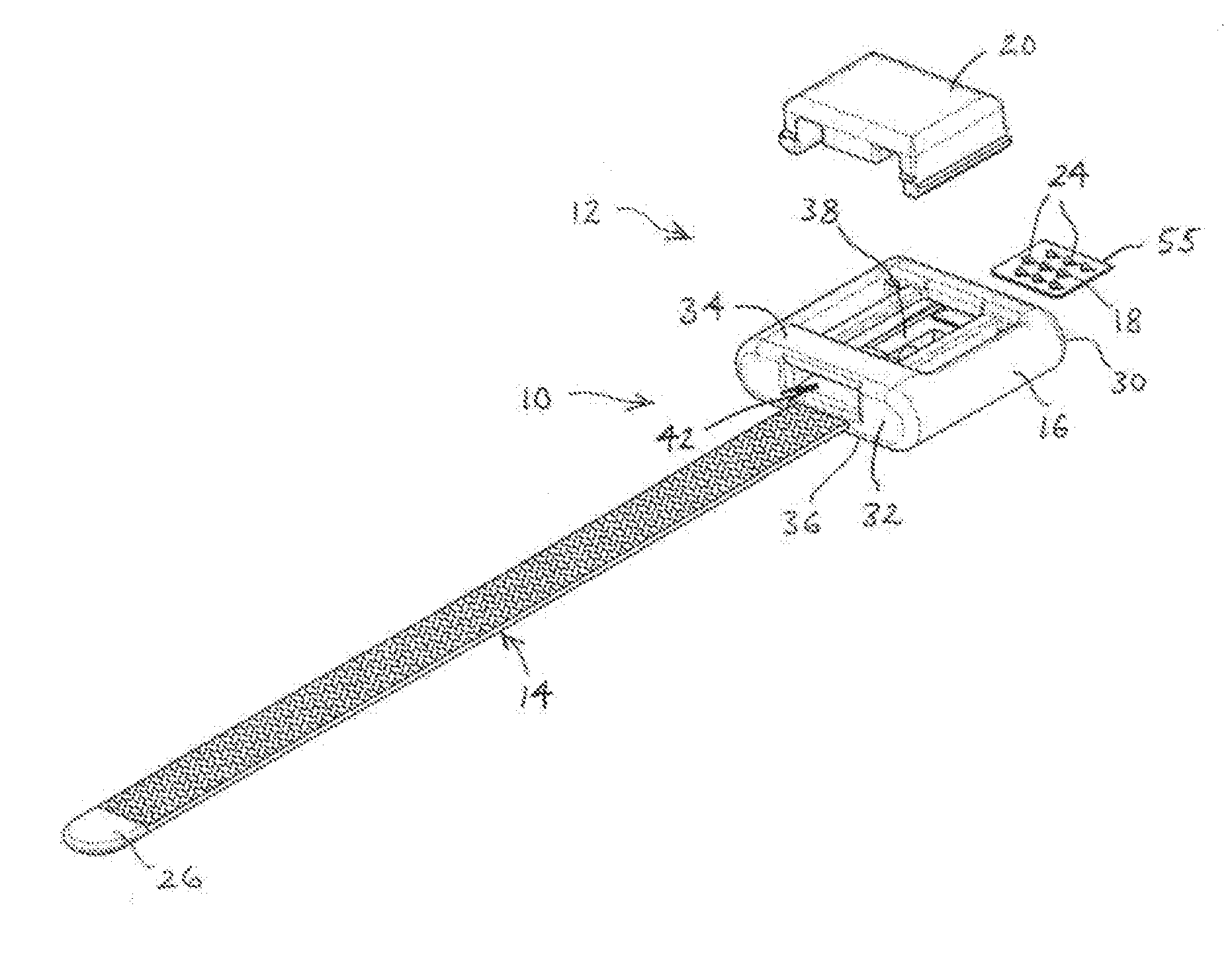
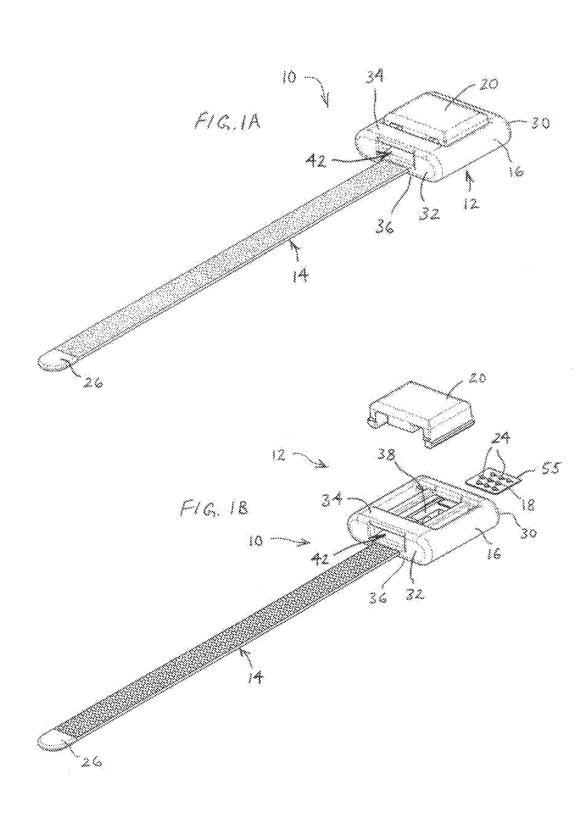
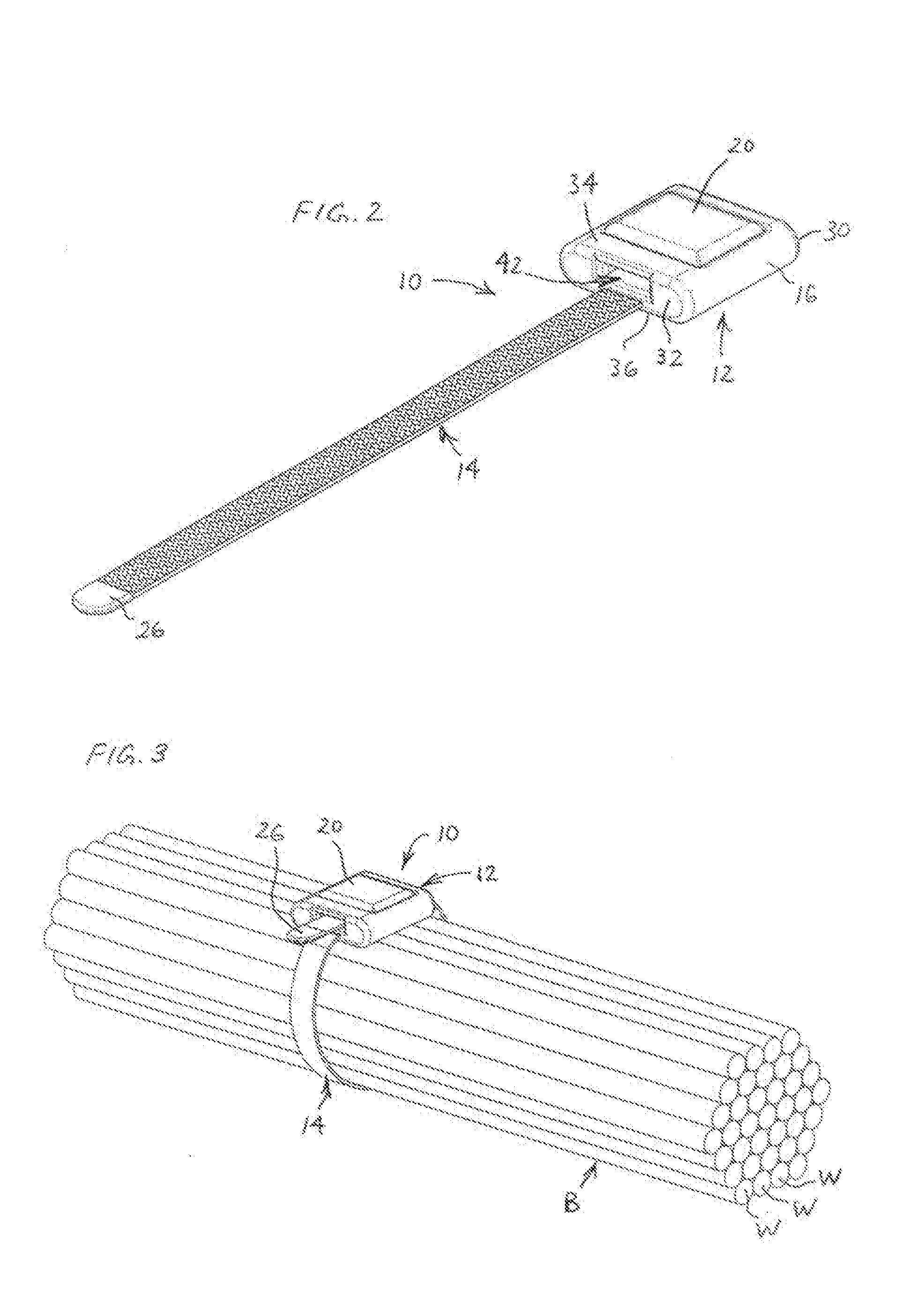
[0065]A first example cable lacing tie device 10 is illustrated in FIGS. 1A, 1B and 2-11. The cable lacing tie device 10 includes a head assembly 12 and a length of cable lacing tape 14. The head assembly 12 of this example includes a molded body 16, a retainer 18 in the form of a retainer plate, and a compression member 20. A first portion 22 of the cable lacing tape 14 is configured to be retained in a first position within the head assembly 12 by having a first end insert-molded within the body 16 in a tortuous path for enhanced retention, as best seen in FIG. 11. A length of the cable lacing tape 14 then extends from the front of the head assembly 12. The cable lacing tie device 10 may be used, for example, to hold together a plurality of objects, such as to form a bundle B of a group of wires W, which are shown in FIG. 3, in a simplified manner.
[0066]The body 16 and compression member 20 preferably each are injection molded and constructed of a material that is suitable for use...
PUM
 Abstract
Description
Claims
Application Information