Scissors with replacement blades and ball bearings

a technology of replacement blades and blades, applied in metal-working equipment, metal-working equipment, manufacturing tools, etc., can solve the problems of lack of versatility of scissors and quick wear of scissors, and achieve the effect of easy replacement, minimal deformation of pivots, and high for

Inactive Publication Date: 2015-05-14
BUCK KNIVES
View PDF4 Cites 17 Cited by
  • Summary
  • Abstract
  • Description
  • Claims
  • Application Information

AI Technical Summary

Benefits of technology

[0006]Embodiments herein are directed to a scissors tool having, for each arm, a concave, curved blade pocket for receiving a replaceable blade. In embodiments, the blades come into contact at an orientation that is parallel to the shear plane and to one another. In addition, embodiments of scissors described herein include a rigid pivot complex that biases the blades together with high force and minimal deformation of the pivot.
[0007]The replaceable blades can be made with various edge angles, serrations and materials for specific tasks, and are easily replaced when they become dull. The blades described in embodiments are flat for ease of manufacture and are assembled into a concave pocket on each of the scissors arms, and then flexed into a bent or bowed configuration by the tightening of a screw near the blade midpoint. Thus, each blade is curved in the direction of a plane where it abuts the other blade, which is also termed the “draw”. The curvature of the scissor arms biases the blades into contact at a cutting point, and a combination of this curvature, elastic deformation of the scissor arms, and the stiffness of the pivot provides high pressure at this point of contact. High contact pressure persists in the full range of motion of the scissors from open to closed.

Problems solved by technology

Scissors are a preferred tool for many tasks because of their versatility, simplicity and ease of use; however, they are often weak when used to cut strong or flexible materials such as thick fabric, wire, cardboard, or heavy fishing line and braided line in particular; and they may wear quickly when used for such demanding tasks.
However, such tools lack the versatility of scissors, and a scissors tool that could generate high cutting power without the aforementioned drawbacks would possess great practical utility.

Method used


Image

  • Scissors with replacement blades and ball bearings
  • Scissors with replacement blades and ball bearings
  • Scissors with replacement blades and ball bearings

Examples


Embodiment Construction

[0028]In the following description, various embodiments of the present invention will be described. For purposes of explanation, specific configurations and details are set forth in order to provide a thorough understanding of the embodiments. However, it will also be apparent to one skilled in the art that the present invention may be practiced without the specific details. Furthermore, well-known features may be omitted or simplified in order not to obscure the embodiment being described.

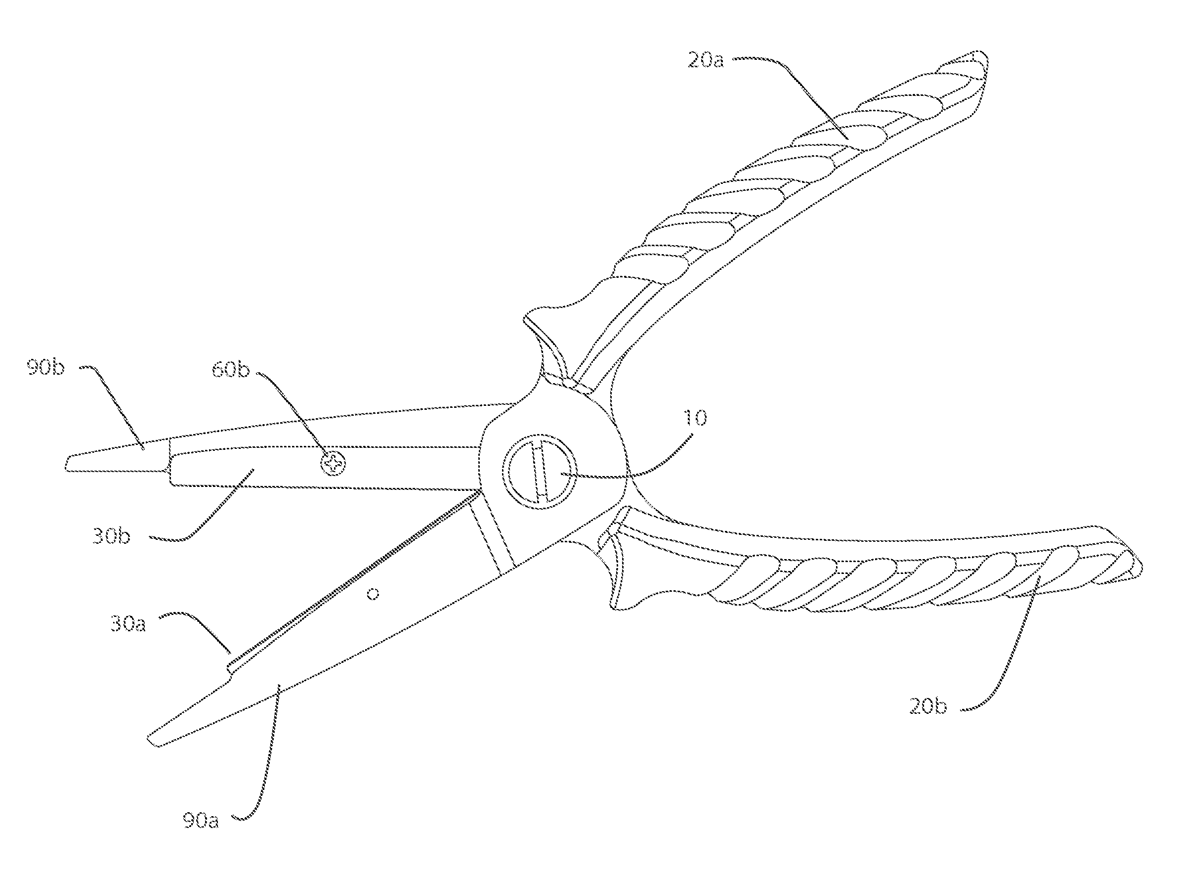
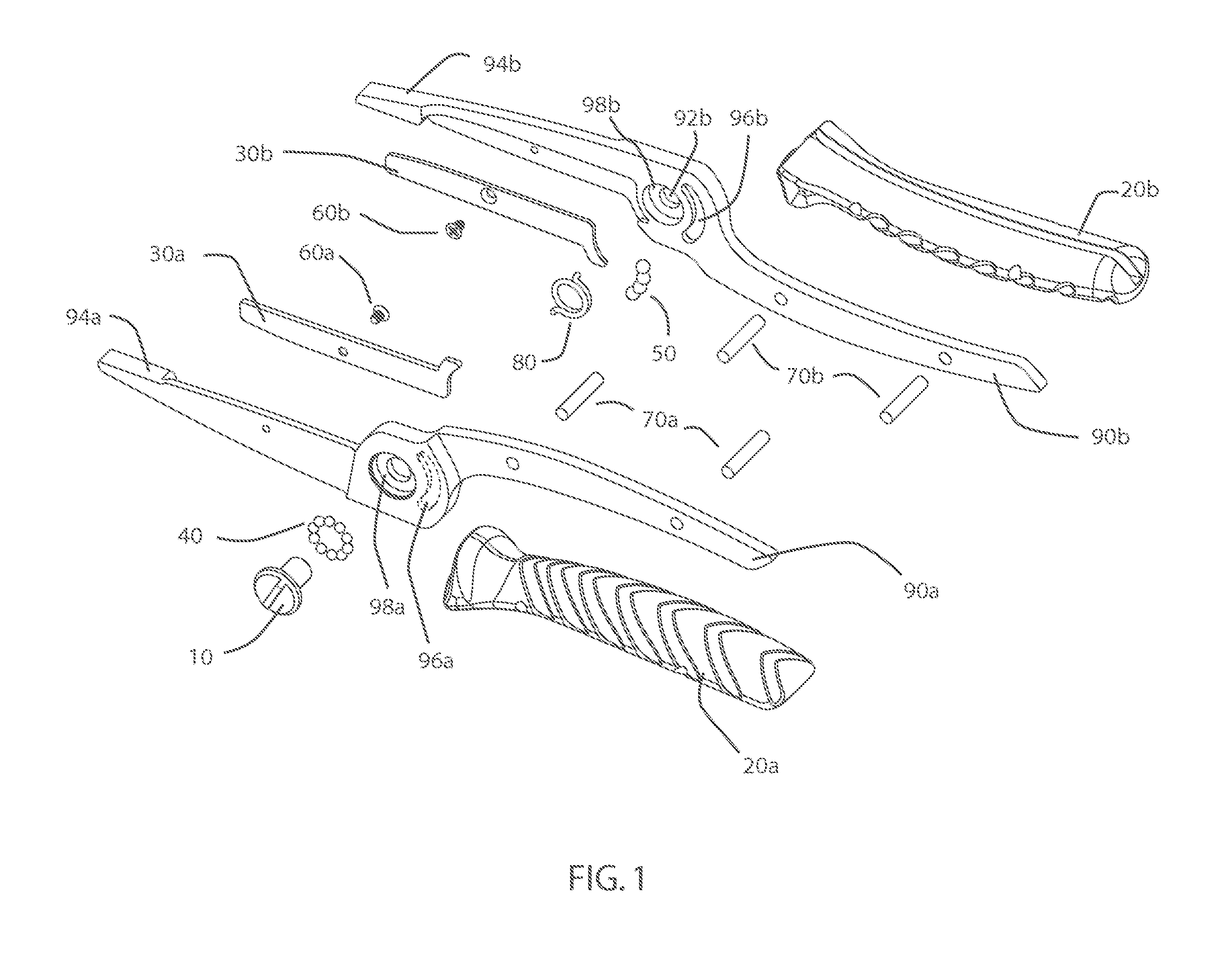
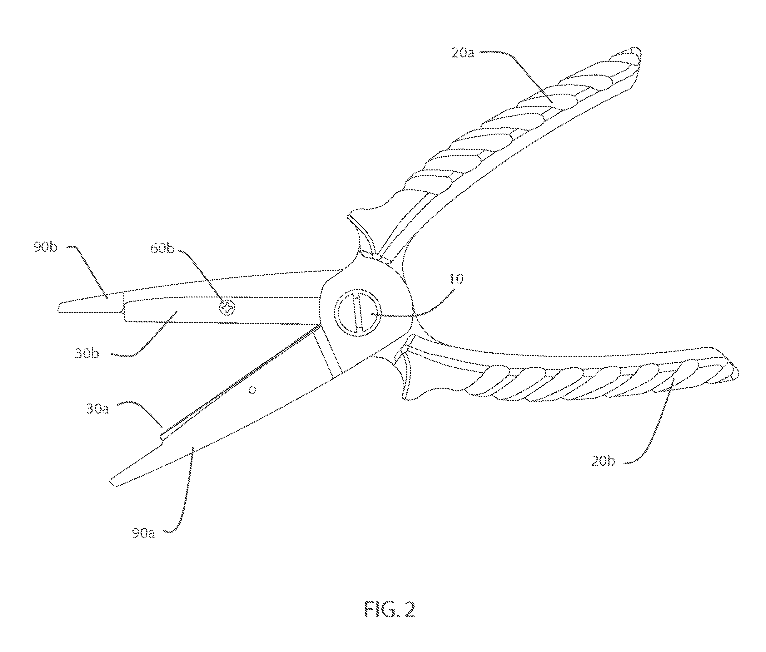
[0029]A popular design for scissors is a configuration having rigid arms which are both structural and cutting members. These arms have cutting edges that are slightly inclined toward one another at the distal end, such that the scissors fit together very tightly when in the closed position and less tightly when open, thus bringing the blades into direct contact only at the cutting point and leaving a gap in the region between the cutting point and pivot. In such designs, the blades tend to be rig...


PUM

PropertyMeasurementUnit
stressaaaaaaaaaa
tensionaaaaaaaaaa
cross-sectional areaaaaaaaaaaa

Abstract

A scissors tool having removable replacement blades and bearings in an arcuate bearing path disposed to stiffen the pivot and bias the blades together with greater inter-blade pressure at the cutting point. In some embodiments, the scissors tool has flexible arms which increase said cutting point edge pressure and provide that little to no gap forms between the blades proximate to and behind the cutting point.

Description

CROSS-REFERENCES TO RELATED APPLICATIONS[0001]The present application claims the benefit of U.S. Provisional Application No. 61 / 903,304 (Attorney Docket No. 88791-884002 (011910US)), filed on Nov. 12, 2013, the full disclosure of which is incorporated herein by reference.BACKGROUND[0002]Scissors are a well known tool. Typically scissors have a pair of handles attached to blades opposite a pivot. When the handles are closed, the blade edges bypass each other in a scissor action for cutting of material in shear.[0003]Scissors are a preferred tool for many tasks because of their versatility, simplicity and ease of use; however, they are often weak when used to cut strong or flexible materials such as thick fabric, wire, cardboard, or heavy fishing line and braided line in particular; and they may wear quickly when used for such demanding tasks. Specialized cutting tools such as wirecutters or shears are often preferred over scissors for difficult jobs, because those tools will generall...

Claims


Application Information

Patent Timeline
Patent Type & Authority Applications(United States)
IPC IPC(8): B26B13/04B26B13/28B26B13/06
CPCB26B13/04B26B13/28B26B13/06B26B13/16Y10T29/49863
Inventor LINN, ERIC P.BOCK, JUSTEN L.
Owner BUCK KNIVES
Why Eureka
Try Eureka