Sky condenser with vertical tube compression and pressurized water utilization

a technology of vertical tube and condenser, which is applied in the direction of greenhouse gas reduction, reciprocating combination engines, jet propulsion mounting, etc., can solve the problems of physical acceleration and deceleration of magnets, and achieve the effect of preventing viscosity or frictional resistan

Inactive Publication Date: 2015-05-14
SCHLAK DANIEL KEITH
View PDF5 Cites 46 Cited by
  • Summary
  • Abstract
  • Description
  • Claims
  • Application Information

AI Technical Summary

Benefits of technology

[0005]Disclosed is a power plant incorporating the attributes of a gas turbine engine, flywheel, and generator (hereafter “TF”) in an integral unit of remarkable compactness, obviating prior art solutions providing three disparate units, consequently reducing the overall weight and volume of hybrid systems. Also disclosed is machinery or a vehicle for use with the TF comprising a pressurized chamber, or pressure accumulator, and supplemental electrical and pressurized apparatus which cooperate to effect a method typically embodied by:

Problems solved by technology

Conversely, movement of the electrons in the coils due to external electromotive forces causes physical acceleration and deceleration of the magnets.

Method used


Image

  • Sky condenser with vertical tube compression and pressurized water utilization
  • Sky condenser with vertical tube compression and pressurized water utilization
  • Sky condenser with vertical tube compression and pressurized water utilization

Examples


Embodiment Construction

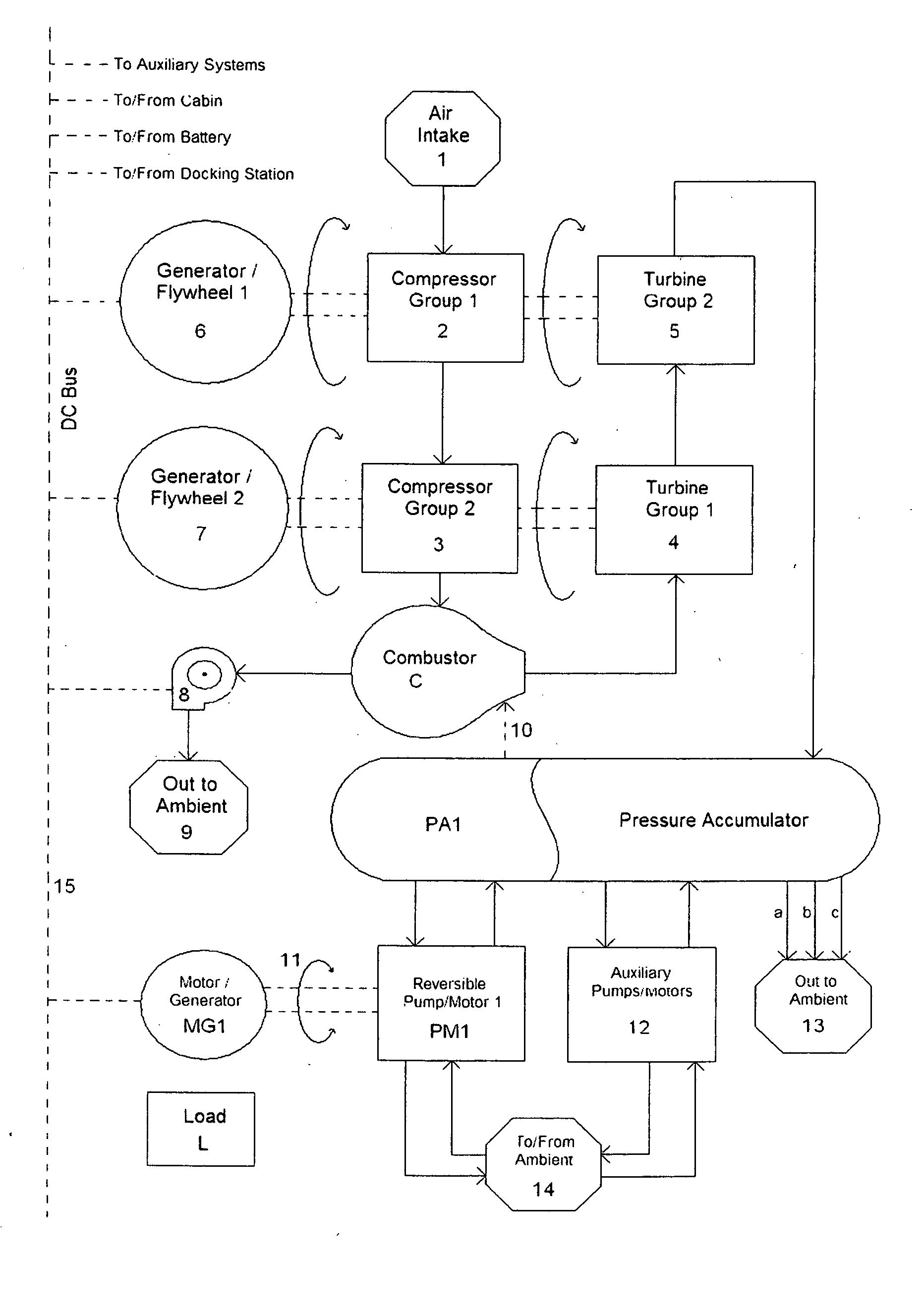
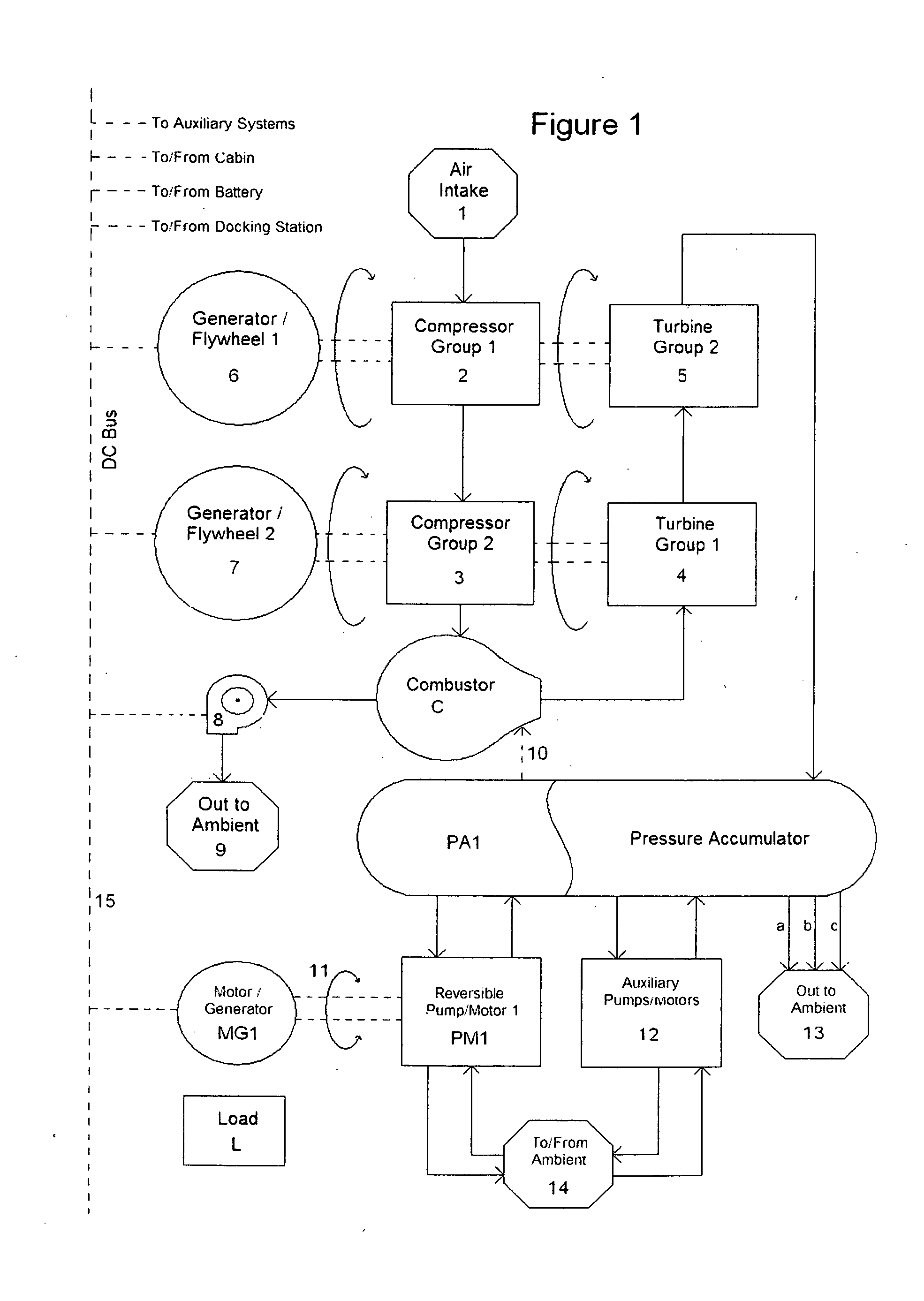
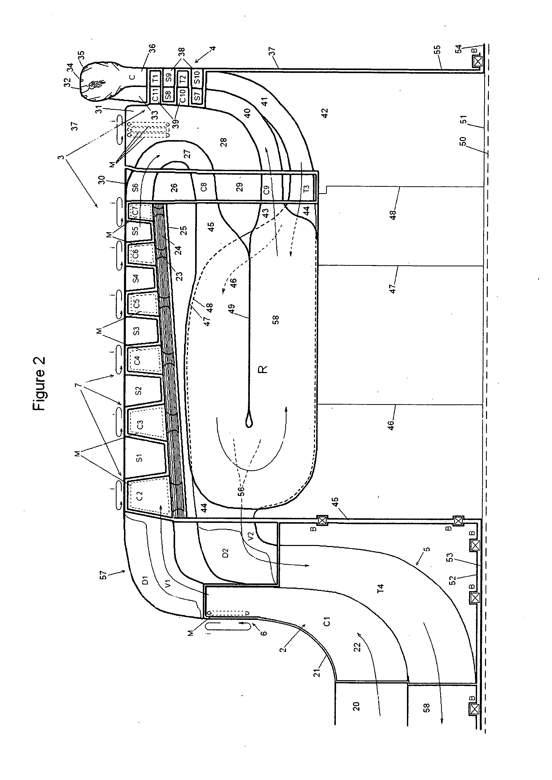
[0137]The following description of FIG. 1 is meant to be understood in conjunction with FIG. 2. The flow chart of FIG. 1 shows the flow of gases through the entire system. Air enters the system from air intake 1 and passes, via a shutter valve (described later) after traversing a heat exchanger (described later) to the first compressor group 2. The air is compressed by first compressor group 2, which is driven by the second turbine group 5 and is integral with the first compressor group 2 and the first generator / flywheel 6. The air passes from the first compressor group 2 to the second compressor group 3, which is driven by the first turbine group 1 and is integral with the second compressor group 3 and the second generator / flywheel 7. In the embodiments of the present application, 2, 5, and 6 are concentrically arranged about a longitudinal axis 50, and 4, 3, and 7 are also concentrically arranged about said longitudinal axis 50. After the second compressor group 3, the compressed ...


PUM


Abstract

A floated condenser extracts water from the sky. The condenser is part of or supplemental to a typical buoyed wind turbine set, comprising lift element, wind turbine, retention cable, electrical output, and base. The cable is hollow or coextensive with a lumen, the inner diameter thereof is water impermeable. The hollow / lumen stacks water over an accumulator, effecting a static base pressure p=ρgh. This pressure makes the water utilizable. After pressure multiplication—via a hydrostatic piston—or not, a first stream of water electrolyzes into liquid hydrogen and oxygen, one or both stored / sold directly. Another stream of water drives a turbine / motor or series hydroelectric turbines / motors, powering electrolysis and / or grid, the water then stored at moderate pressure for water utilities. Excess power from the wind turbine also supplements electrical output. A conductor runs along the cable. Gasified hydrogen is routed via the cable, lifting the condenser / turbine / kite.

Description

RELATED APPLICATIONS[0001]This application is a Continuation-in-Part of, and claims Continuation-in-Part status and priority of U.S. Nonprovisional application Ser. No. 13 / 506,962, filed May 27, 2012, entitled “Integral Gas turbine, Flywheel, Generator, and Method for Hybrid Operation Thereof”.BACKGROUND SUMMARY[0002]Power plants typically produce peak power within a single prescribed operating range. This range is a design specification and invariably operation outside it is undesired. In instances requiring high power production, performance while underloaded is a secondary consideration and often the inefficiencies associated therewith are written off, as negligible in some instances such as wherein underloaded conditions are only encountered at the beginning and end of a long cycle. In some applications, the upper loading range can be an order of magnitude, or more, higher than the underloaded range. It is the inventor's understanding that the prior art is insufficient in offeri...

Claims


Application Information

Patent Timeline
Patent Type & Authority Applications(United States)
IPC IPC(8): F03B13/00
CPCF03B13/00F05B2220/61F05B2240/917F05B2240/922F01D1/06F03D9/00F02C3/045F02C3/05F02C3/08F02C3/14Y02E10/728F03D13/20Y10S74/08Y10T74/20012Y02E60/16Y02E60/36Y02T50/60Y02E10/72Y02E70/30B64D33/00B64C29/0041F02D25/00B64C29/0091B64C29/0016B60K5/08B64C27/52B64D31/00B64C27/22B64C29/0083B64C27/08B64C29/00F03D9/32F03D9/17F03D9/19F03D9/25F03D15/10F03D80/60
Inventor SCHLAK, DANIEL KEITH
Owner SCHLAK DANIEL KEITH
Why Eureka
Try Eureka