Integral gas turbine, flywheel, generator, and method for hybrid operation thereof

a gas turbine and hybrid technology, applied in the direction of machines/engines, sustainable transportation, mechanical equipment, etc., can solve the problems of physical acceleration and deceleration of magnets, and achieve the effects of reducing the number of moving parts, high pressure, and optimal power production

Inactive Publication Date: 2017-01-10
SCHLAK DANIEL K
View PDF87 Cites 7 Cited by
  • Summary
  • Abstract
  • Description
  • Claims
  • Application Information

AI Technical Summary

Benefits of technology

[0005]Disclosed is a power plant incorporating the attributes of a gas turbine engine, flywheel, and generator (hereafter “TF”) in an integral unit of remarkable compactness, obviating prior art solutions providing three disparate units, consequently reducing the overall weight and volume of hybrid systems. Also disclosed is machinery or a vehicle for use with the TF comprising a pressurized chamber, or pressure accumulator, and supplemental electrical and pressurized apparatus which cooperate to effect a method typically embodied by:
[0014]One thing should be pointed out concerning the novel power plant geometry. All stages are arranged to, when the main unit is sealed off, force air toward the combustor. With proper placement of bypass valves—specifically inter-stage seals that automatically leak when a pressure-drop across them falls below a threshold—the power-plant, not only efficient in its use of space, evacuates itself much more quickly from a single bleed point (preferably in the combustor) than traditional (linear axial) systems ever could, further reducing the number of moving parts. Again, the TF charges an accumulator, the pressure in the accumulator drives a pump, the pump, TF, and utility motors direct electrical energy away from and toward each other along a DC bus. A heat exchanger directs the initial intake air past the air traveling from the last turbine stage to the accumulator. Further, a recuperator can be advantageously positioned to heat the combustor inlet with a turbine outlet. The recuperator, the heat exchanger, and supplemental heat exchanges inside the accumulator, such as the heating of fuel, should sufficiently cool the exhaust air so that it does not harm the chamber, which is desired since the materials best suited for the accumulator due to their tensile-strength-to-weight ratios decompose at high temperatures.
[0017]However, the advantage of the DC bus is that it obviates transmissions and clutches, and any shafts, axles, gears, levers, housings, collars, and cooling and lubricating systems associated therewith. A control system will actuate small switches and corresponding governors of current, such that the consumers and producers always operate at the most efficient, or demanded, speed and torque. For the TF during flywheel stage, this speed is much higher than is achievable by the fluid reaction on the turbine vanes. The traction motors can decelerate the vehicle (if it is a vehicle the system is being used in) or accelerate it, regardless of speed of the vehicle, and the TF can always be accelerated, despite the fact that it might already be rotating very quickly, as the torque on the main compressor / turbine group will always be proportional to voltage applied, since the incoming electrical energy will always be oscillated with a frequency, and timing, perfectly attuned. The methods for doing this are well known in the electrical arts.
[0025]For instance, the shock absorbers, in the event that the machinery is a vehicle, can feed the main chamber via means known by prior US patents. Particularly in the embodiment of an automobile, a simple leading arm with a chain- or belt driven wheel receiving motive power from a motor along the arm, while up and down perturbations experience due to contours in the road cause movement against a piston and spring, heightens the hybrid aspects of the foreseen embodiments. Following the teachings of said patents, the initial deflection of the rod will charge the chamber, as will the reaction by the spring to home the rod. The chamber, being ubiquitous, is ready and willing to assume this energy for future use, and the acceleration it later provides will almost negate the deceleration caused by the contour. It is expected that this provision will more than make up for the added cost and weight associated with replacing a typical shock absorber with one of said patents, however they were disused in their own time.Mode-Change: From Hybrid Operation to High-Consumer Operation

Problems solved by technology

Conversely, movement of the electrons in the coils due to external electromotive forces causes physical acceleration and deceleration of the magnets.

Method used


Image

  • Integral gas turbine, flywheel, generator, and method for hybrid operation thereof
  • Integral gas turbine, flywheel, generator, and method for hybrid operation thereof
  • Integral gas turbine, flywheel, generator, and method for hybrid operation thereof

Examples


Embodiment Construction

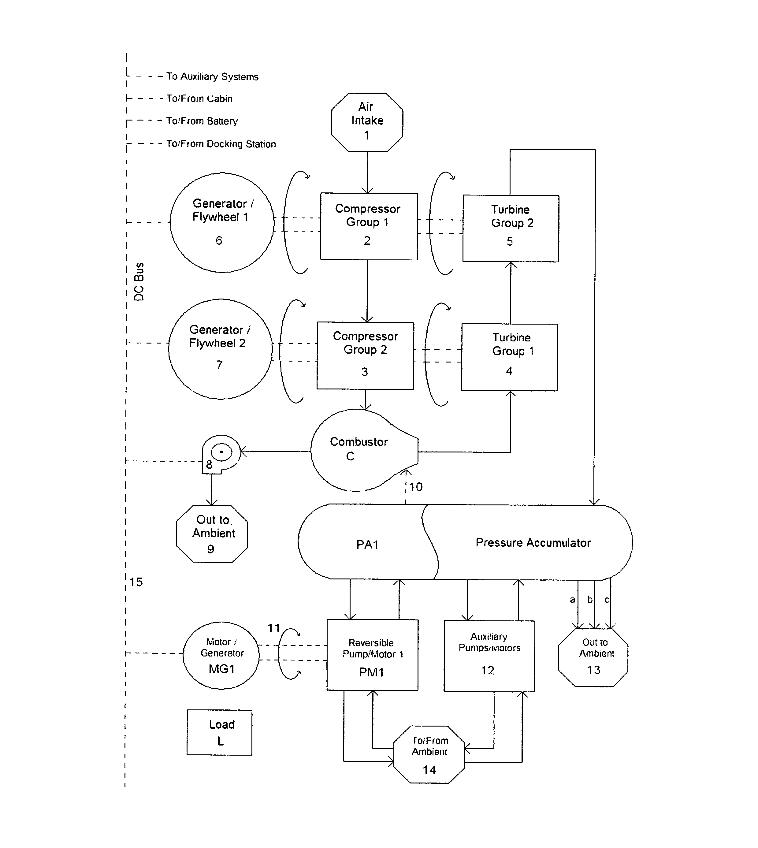
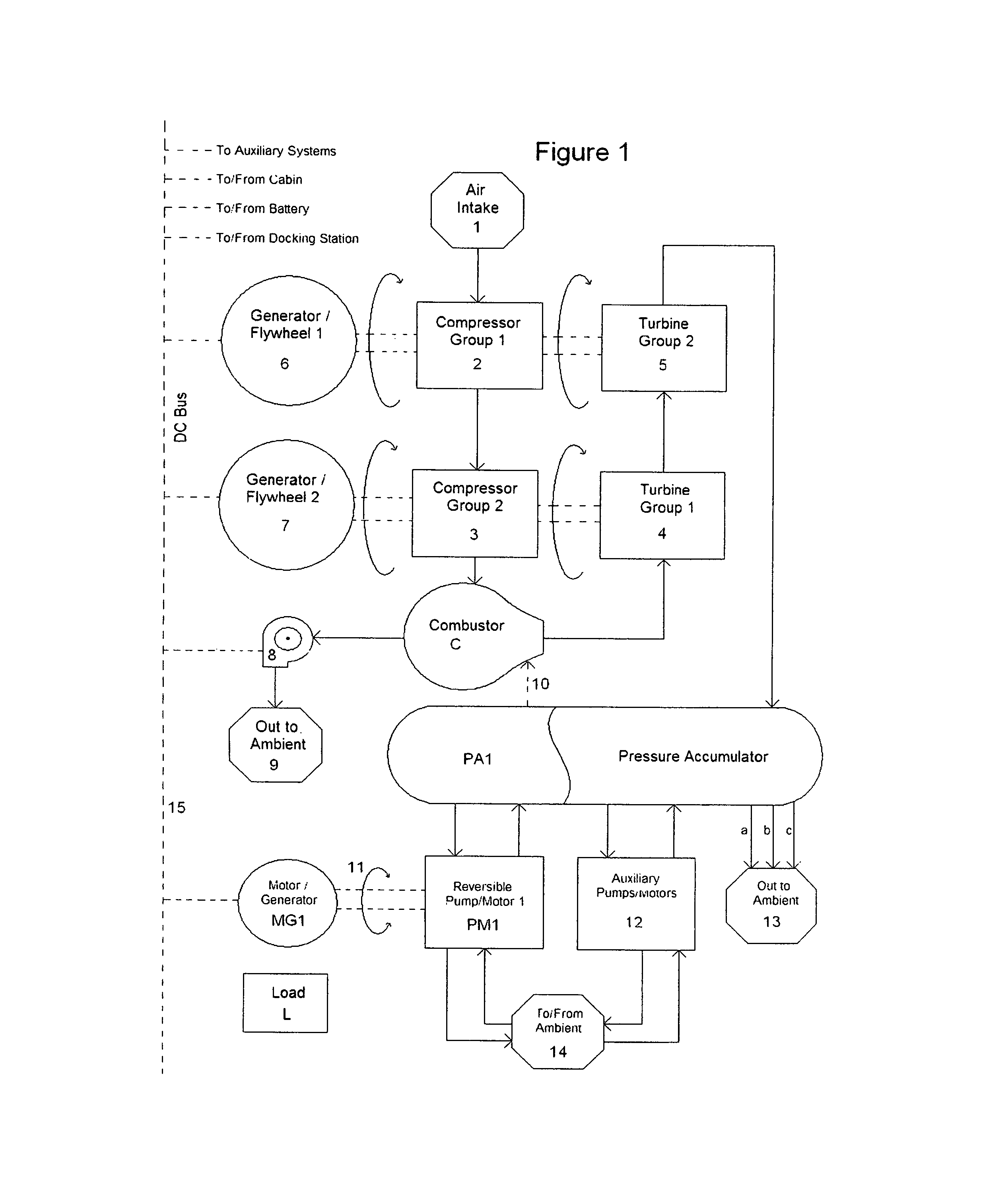
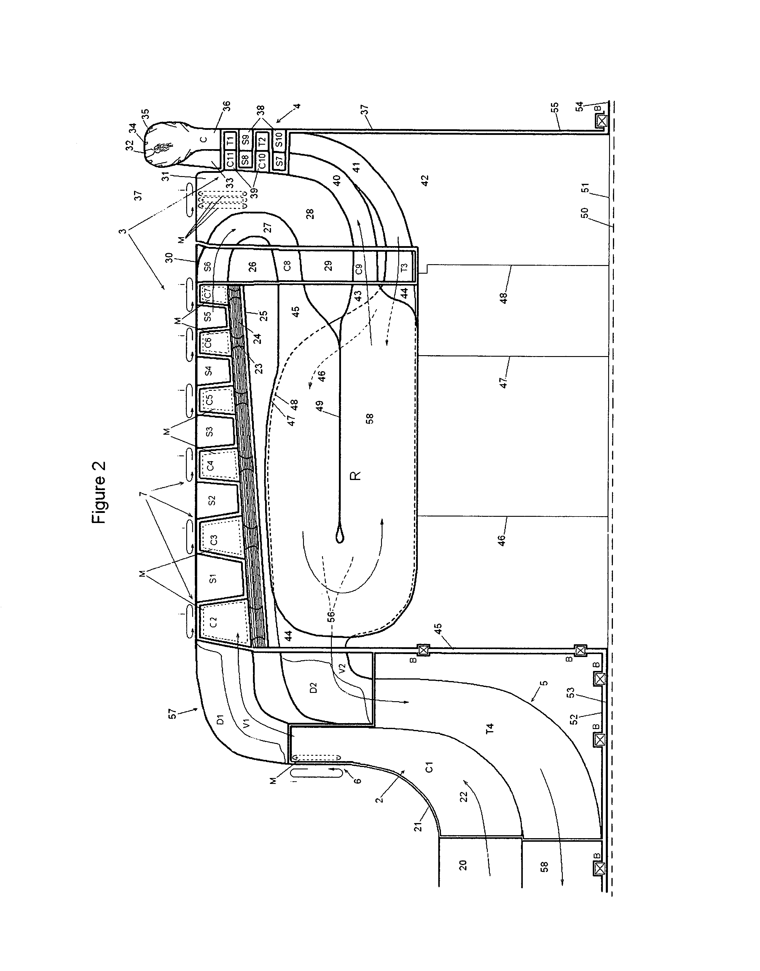
[0077]The following description of FIG. 1 is meant to be understood in conjunction with FIG. 2. The flow chart of FIG. 1 shows the flow of gases through the entire system. Air enters the system from air intake 1 and passes, via a shutter valve (described later) after traversing a heat exchanger (described later) to the first compressor group 2. The air is compressed by first compressor group 2, which is driven by the second turbine group 5 and is integral with the first generator / flywheel 6. The air passes from the first compressor group 2 to the second compressor group 3, which is driven by the first turbine group 1 and is integral with the second generator / flywheel 7. In the embodiments of the present application, 2, 5, and 6 are concentrically arranged about a longitudinal axis 50, and 4, 3, and 7 are also concentrically arranged about said longitudinal axis 50. After the second compressor group 3, the compressed air enters a combustor C, which for this discussion can be seen as ...


PUM


Abstract

A power plant incorporating attributes of a gas turbine engine, flywheel, and electrical generator (hereafter turbine / flywheel or TF) in a single compact unit, having a compressor arrayed with magnets which weight the periphery of the TF. Intermittent combustion periods accelerate the TF to a first rotational velocity, then combustion ceases, and the inlet / outlet of the TF are sealed, causing it to self-evacuate. Conductive coils surround the TF. Magnetic flux between the magnets and coils acts as a motor / generator, electrically powering a load, and absorbing electrical power therefrom via regenerative braking; power out decelerating the TF (now a flywheel), power in accelerating it. A pressure accumulator accepts the TF exhaust, and is pressurized by the combustion periods. Between combustion periods, exhaust in the accumulator expands in a small pump / motor that drives a generator, routing electricity to the TF to raise its rotational velocity.

Description

RELATED APPLICATIONS[0001]This application claims priority of U.S. Provisional Application Ser. No. 61 / 457,755, filed May 27, 2011, entitled “Integral Gas turbine, Flywheel, Generator, and Method for Hybrid Operation Thereof”.BACKGROUND SUMMARY[0002]Power plants typically produce peak power within a single prescribed operating range. This range is a design specification and invariably operation outside it is undesired. In instances requiring high power production, performance while underloaded is a secondary consideration and often the inefficiencies associated therewith are written off, as negligible in some instances such as wherein underloaded conditions are only encountered at the beginning and end of a long cycle. In some applications, the upper loading range can be an order of magnitude, or more, higher than the underloaded range. It is the inventor's understanding that the prior art is insufficient in offering a single power plant offering plural optimal operating ranges wher...

Claims


Application Information

Patent Timeline
Patent Type & Authority Patents(United States)
IPC IPC(8): F02C3/00F01D15/02F01D15/10F02C5/02F02C6/16F02C7/36F02C7/08
CPCF02C3/00F01D15/02F01D15/10F02C5/02F02C6/16F02C7/08F02C7/36F05D2220/90Y02T50/671Y02E60/16Y02T50/60
Inventor SCHLAK, DANIEL KEITH
Owner SCHLAK DANIEL K
Why Eureka
Try Eureka