Flywheel with Inner Turbine, Intermediate Compressor, and Outer Array of Magnets

a technology of compressors and flywheels, applied in the direction of efficient propulsion technologies, machines/engines, liquid fuel engines, etc., can solve the problems of physical acceleration and deceleration of magnets, and achieve the effect of preventing viscosity or frictional resistan

Inactive Publication Date: 2017-06-22
SCHLAK DANIEL
View PDF14 Cites 19 Cited by
  • Summary
  • Abstract
  • Description
  • Claims
  • Application Information

AI Technical Summary

Benefits of technology

[0029]When the main shaft MS and high-consumer drive shaft have equivalent rotational velocities (not necessarily zero, as discussed later), a sleeve or collar associated with a differential (or similar torque transfer mechanism) associated with the drive shaft will be forced in a longitudinal direction (relative to the main shaft), to mate with a protrusion structure on the main shaft In some applications a slot or groove, or a plurality of either, will embrace a trunnion or like, or a plurality thereof, on the main shaft. In other applications, the main shaft will be splined on its outer diameter, and the sleeve/collar machined on its inner diameter to interfit, or vice versa. Other embodiments are foreseen. Countless arrangements are known to those of ordinary skill in the art for engaging a shaft to torque transfer means when their speeds are matched during engagement, and the simplest is of co...

Problems solved by technology

Conversely, movement of the electrons in the coils due to external elec...

Method used


Image

  • Flywheel with Inner Turbine, Intermediate Compressor, and Outer Array of Magnets
  • Flywheel with Inner Turbine, Intermediate Compressor, and Outer Array of Magnets
  • Flywheel with Inner Turbine, Intermediate Compressor, and Outer Array of Magnets

Examples


Embodiment Construction

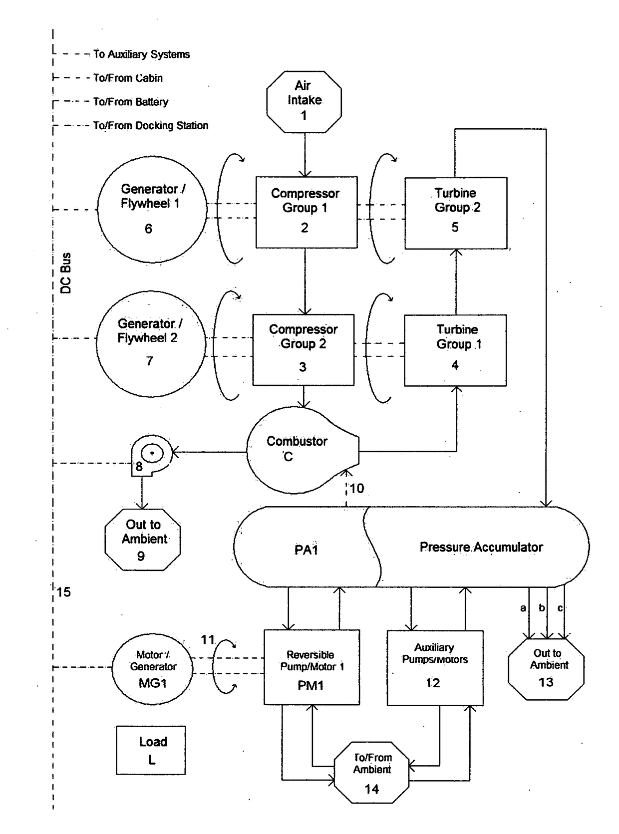
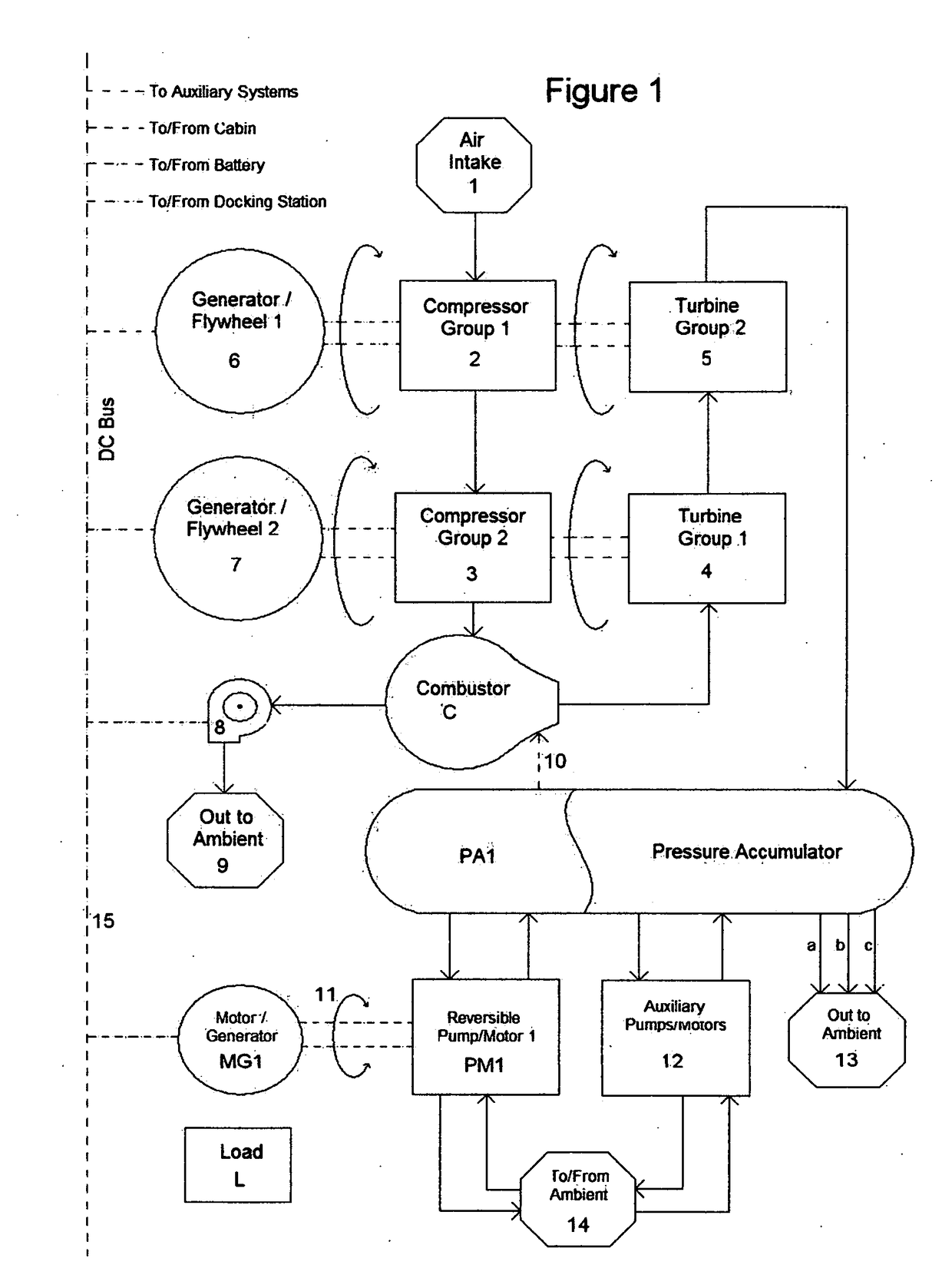
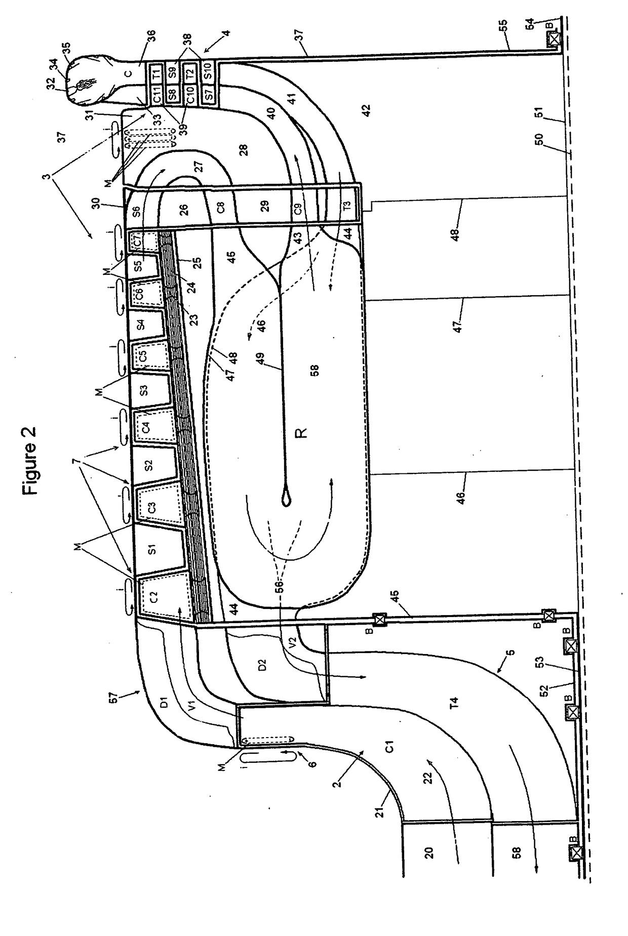
[0137]The following description of FIG. 1 is meant to be understood in conjunction with FIG. 2. The flow chart of FIG. 1 shows the flow of gases through the entire system. Air enters the system from air intake 1 and passes, via a shutter valve (described later) after traversing a heat exchanger (described later) to the first compressor group 2. The air is compressed by first compressor group 2, which is driven by the second turbine group 5 and is integral with the first compressor group 2 and the first generator / flywheel 6. The air passes from the first compressor group 2 to the second compressor group 3, which is driven by the first turbine group 1 and is integral with the second compressor group 3 and the second generator / flywheel 7. In the embodiments of the present application, 2, 5, and 6 are concentrically arranged about a longitudinal axis 50, and 4, 3, and 7 are also concentrically arranged about said longitudinal axis 50. After the second compressor group 3, the compres...


PUM


Abstract

A flywheel is provided in combination with a hybrid machine, wherein said flywheel comprises, in a radial direction, from inward to outward, an inner turbine, an intermediate compressor, and an outer array of magnets. The turbine cooperates with said hybrid machine to spin faster when said machine decelerates, and slower when said machine accelerates. An inner turbine drives both said intermediate compressor and said hybrid machine. The outer array of magnets is driven by said hybrid machine to accelerate the flywheel to accelerate the flywheel during braking of said hybrid machine. Said hybrid machine communicates with said flywheel to house it and render energy from it, in a hybrid manner such that energy is stored in a pressure or electrical storage mode, or both pressure and electrical storage mode, to effect a regenerative mode that attains low fuel consumption.

Description

RELATED APPLICATIONS[0001]This application is a Continuation of U.S. Non-provisional application Ser. No. 13 / 998,564, filed Nov. 12, 2013, entitled “Sky Condenser with Vertical Tube Compression and Pressurized Water Utilization”, which is itself a Continuation-in-Part of, and claims Continuation-in-Part status and priority of, U.S. Non-provisional application Ser. No. 13 / 506,962, filed May 29, 2012, entitled “Integral Gas turbine, Flywheel, Generator, and Method for Hybrid Operation Thereof”, which itself claims priority of U.S. Provisional Application No. 61 / 457,755, filed May 27, 2011, entitled “Integral Gas Turbine, Flywheel, Generator, and Method for Hybrid Use Thereof”.BACKGROUND SUMMARY[0002]Power plants typically produce peak power within a single prescribed operating range. This range is a design specification and invariably operation outside it is undesired. In instances requiring high power production, performance while underloaded is a secondary consideration and often th...

Claims


Application Information

Patent Timeline
IPC IPC(8): F01D15/10H02K7/18F02C3/04F02B37/00F02B33/40B64D27/10F01D5/02F01D9/04F04D29/32F04D29/54H02K7/02B64C13/02
CPCF01D15/10H02K7/025H02K7/1823F02C3/04F02B37/00B64C13/02F05D2220/76F01D5/02F01D9/041F04D29/321F04D29/542F02B33/40F05D2220/32B64D27/10F01D5/041F01D15/02F02C3/045F02C3/05F02C3/08F04D25/0606F04D29/284F04D29/324H02K7/1807H02K53/00Y02E60/16Y02T10/12Y02T50/60
Inventor SCHLAK, DANIEL
Owner SCHLAK DANIEL
Why Eureka
Try Eureka