Vertical takeoff and landing aircraft and gas turbine engine with fan thrust and exhaust thrust delivered downwardly

a technology of vertical landing and gas turbine engine, which is applied in the direction of vertical landing/take-off aircraft, transportation and packaging, power plant types, etc., can solve the problems of physical acceleration and deceleration of magnets, and achieve the effect of reducing the number of moving parts, high pressure and optimal power production

Inactive Publication Date: 2017-06-08
SCHLAK DANIEL KEITH
View PDF0 Cites 3 Cited by
  • Summary
  • Abstract
  • Description
  • Claims
  • Application Information

AI Technical Summary

Benefits of technology

[0014]One thing should be pointed out concerning the novel power plant geometry. All stages are arranged to, when the main unit is sealed off, force air toward the combustor. With proper placement of bypass valves—specifically inter-stage seals that automatically leak when a pressure-drop across them falls below a threshold—the power-plant, not only efficient in its use of space, evacuates itself much more quickly from a single bleed point (preferably in the combustor) than traditional (linear axial) systems ever could, further reducing the number of moving parts. Again, the TF charges an accumulator, the pressure in the accumulator drives a pump, the pump, TF, and utility motors direct electrical energy away from and toward each other along a DC bus. A heat exchanger directs the initial intake air past the air traveling from the last turbine stage to the accumulator. Further, a recuperator can be advantageously positioned to heat the combustor inlet with a turbine outlet. The recuperator, the heat exchanger, and supplemental heat exchanges inside the accumulator, such as the heating of fuel, should sufficiently cool the exhaust air so that it does not harm the chamber, which is desired since the materials best suited for the accumulator due to their tensile-strength-to-weight ratios decompose at high temperatures.
[0015]During sustained high power output all available power is directed to the compressor/turbine module attached to a main drive shaft. In the preferred embodiment, the first turbine stage produces work whose sum is delivered to said shaft after having the work of the axial compressor stages subtracted therefrom. Also, in the preferred embodiment, the second turbine group, of the centrifugal type, drives the

Problems solved by technology

Conversely, movement of the electrons in the coils due to external electro

Method used


Image

  • Vertical takeoff and landing aircraft and gas turbine engine with fan thrust and exhaust thrust delivered downwardly
  • Vertical takeoff and landing aircraft and gas turbine engine with fan thrust and exhaust thrust delivered downwardly
  • Vertical takeoff and landing aircraft and gas turbine engine with fan thrust and exhaust thrust delivered downwardly

Examples


Embodiment Construction

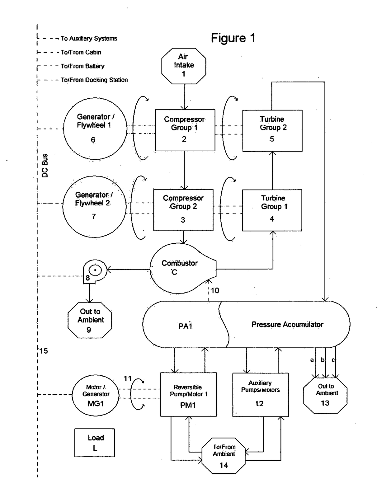
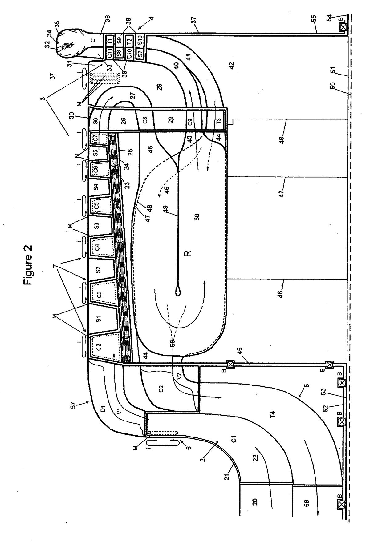
[0077]The following description of FIG. 1 is meant to be understood in conjunction with FIG. 2. The flow chart of FIG. 1 shows the flow of gases through the entire system. Air enters the system from air intake 1 and passes, via a shutter valve (described later) after traversing a heat exchanger (described later) to the first compressor group 2. The air is compressed by first compressor group 2, which is driven by the second turbine group 5 and is integral with the first generator / flywheel 6. The air passes from the first compressor group 2 to the second compressor group 3, which is driven by the first turbine group 1 and is integral with the second generator / flywheel 7. In the embodiments of the present application, 2, 5, and 6 are concentrically arranged about a longitudinal axis 50, and 4, 3, and 7 are also concentrically arranged about said longitudinal axis 50. After the second compressor group 3, the compressed air enters a combustor C, which for this discussion can be seen as ...


PUM


Abstract

An aircraft airfoil or wing or fuselage MODULE is fitted with a gas turbine engine driving a fan or propeller, in combination with a gaseous pressure accumulator, wherein said fan or propeller and said gaseous pressure accumulator both provide thrust, said fan thrust being provided from a rear of the MODULE via a drop-down thrust vectoring panel and said gaseous pressure accumulator thrust being provided from a fore of said MODULE, wherein the gaseous pressure accumulator is supplied with exhaust from said gas turbine engine and said exhaust is delivered downwardly at a variable angle, and said thrust vectoring panel is a panel with multiple minor panels which vector fan thrust at more than one angle. The gas turbine engine exhaust is delivered forwardly of said fan or propeller exhaust.

Description

RELATED APPLICATIONS[0001]This application is a continuation application claiming priority of U.S. Non-Provisional application Ser. No. 13 / 506,962, filed May 29, 2012 and entitled “Integral Gas Turbine, Flywheel, Generator, and Method for Hybrid Operation Thereof”, which itself claims priority of U.S. Provisional Application Ser. No. 61 / 457,755, filed May 27, 2011, entitled “Integral Gas Turbine, Flywheel, Generator, and Method for Hybrid Use Thereof”.BACKGROUND SUMMARY[0002]Power plants typically produce peak power within a single prescribed operating range. This range is a design specification and invariably operation outside it is undesired. In instances requiring high power production, performance while underloaded is a secondary consideration and often the inefficiencies associated therewith are written off, as negligible in some instances such as wherein underloaded conditions are only encountered at the beginning and end of a long cycle. In some applications, the upper loadin...

Claims


Application Information

Patent Timeline
IPC IPC(8): B64C29/00
CPCB64C29/0075B64C29/0025B64C29/0033B64C37/00B64D27/12B64D35/02Y02T50/40
Inventor SCHLAK, DANIEL KEITH
Owner SCHLAK DANIEL KEITH
Why Eureka
Try Eureka