Pressure sensor

Active Publication Date: 2015-05-14
DENSO CORP
View PDF9 Cites 22 Cited by
  • Summary
  • Abstract
  • Description
  • Claims
  • Application Information

AI Technical Summary

Benefits of technology

[0025]In the pressure sensor, each of the first gauge resistor to the fourth gauge resistor is formed by a combined resistance in which a piezoresistive element to which a large thermal stress is applied and a piezoresistive element to which a small thermal stress is applied are serially connected to each other. Thus, when the thermal stress is generated in the diaphragm, th

Problems solved by technology

Thus, an error of the amplified signal becomes larger as an absolute value of the maximum va

Method used


Image

  • Pressure sensor
  • Pressure sensor
  • Pressure sensor

Examples


Example

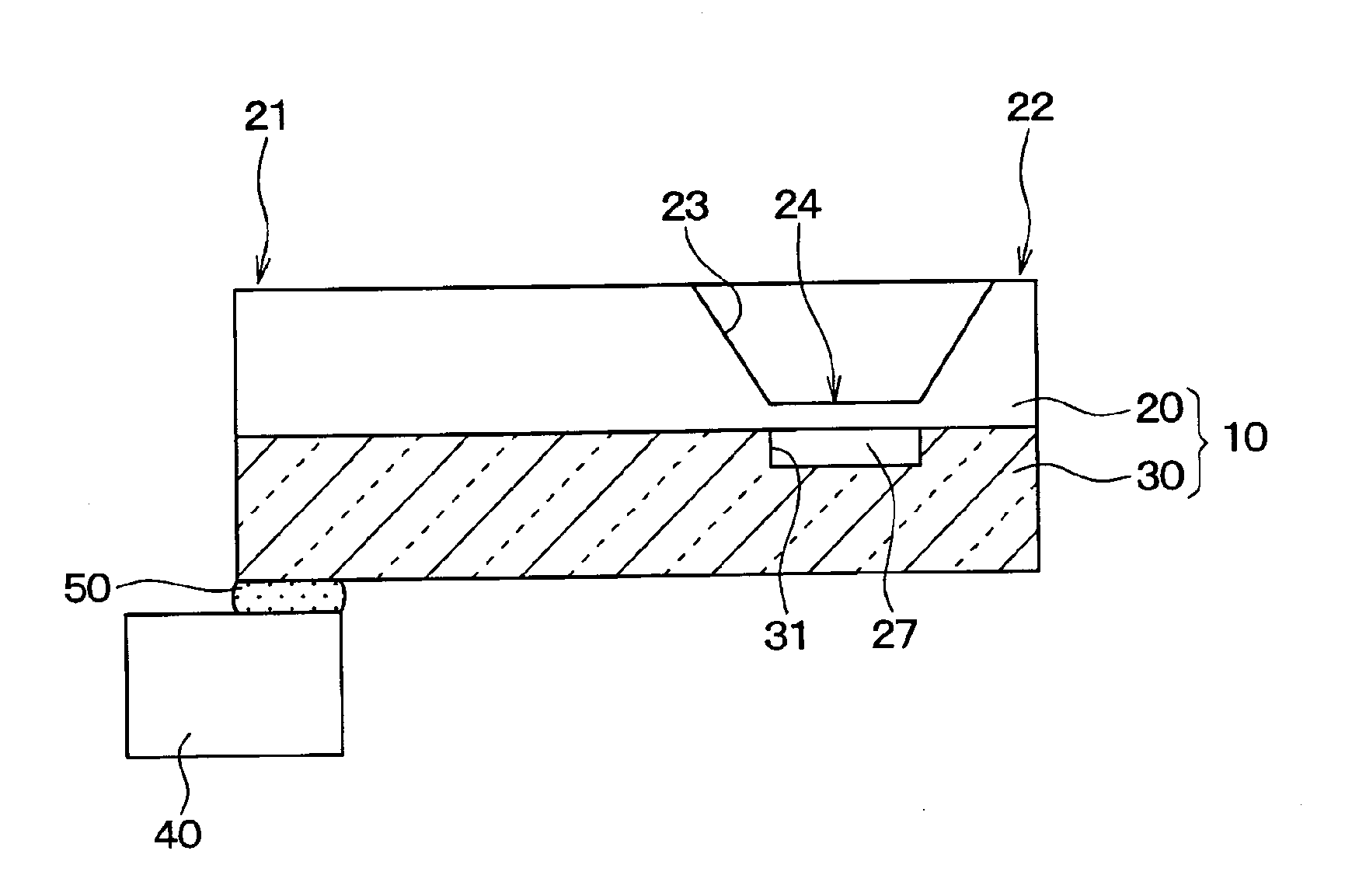
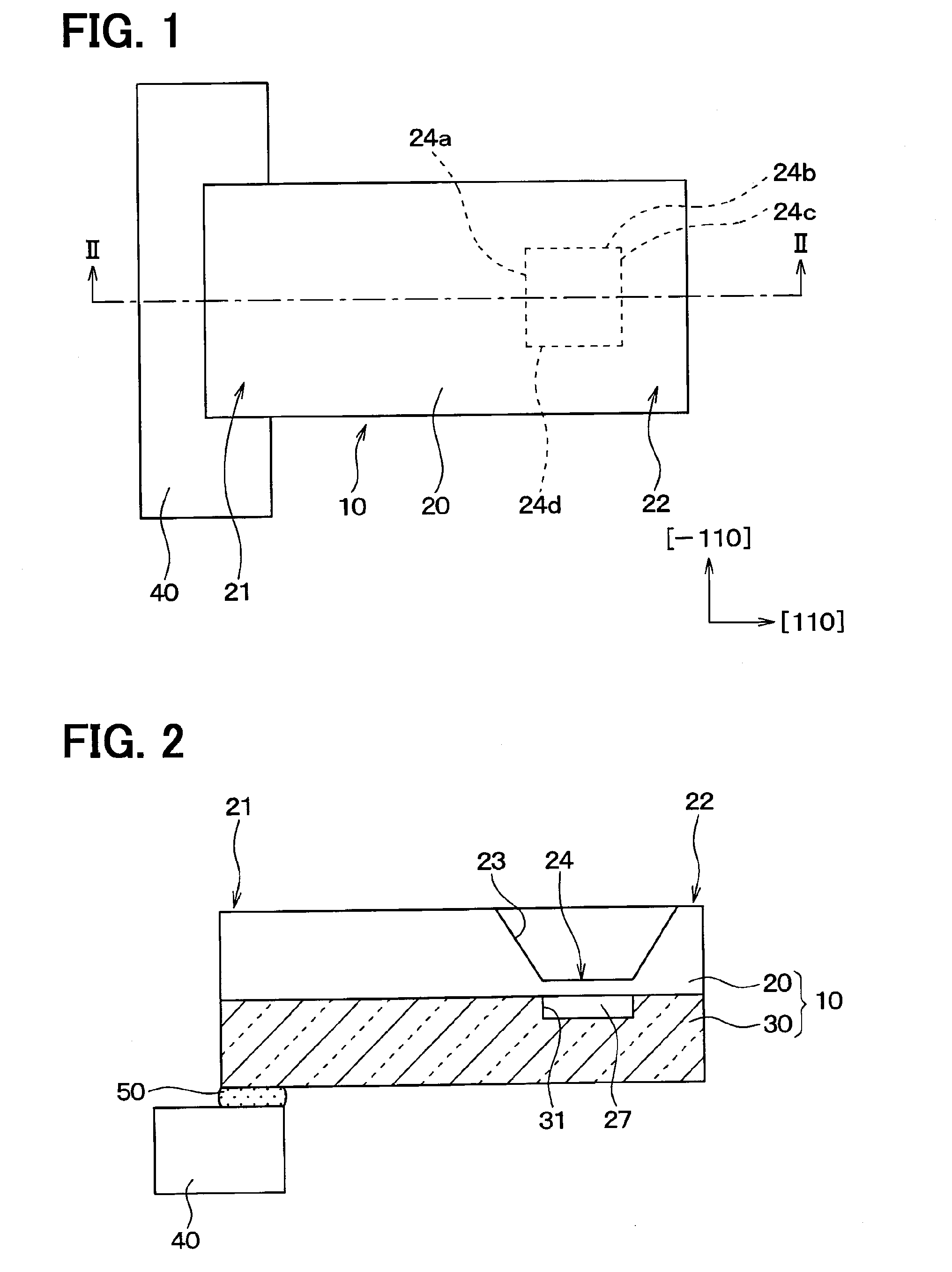
[0060]A first embodiment of the present disclosure will be described. As shown in FIGS. 1 and 2, a pressure sensor includes a sensor section 10, and a support member 40 that is formed of a resin material or the like and cantilever-supports the sensor section 10.

[0061]The sensor section 10 includes a silicon substrate 20 and a base 30 such as a glass substrate, and has a rectangular parallelepiped shape in which one direction thereof is a longitudinal direction. One end in the longitudinal direction is a fixed end 21, and the other end opposite to the one end is a free end 22. Further, the fixed end 21 is bonded to the support member 40 through a bonding member 50 such as an adhesive. That is, the sensor section 10 is cantilever-supported by the support member 40. The longitudinal direction of the sensor section 10 refers to a direction along the direction.

[0062]The silicon substrate 20 is formed in the rectangular parallelepiped shape. In the present embodiment, a main surface there...

Example

Second Embodiment

[0095]A second embodiment of the present disclosure will be described. A pressure sensor according to the present embodiment is configured so that the shape of the diaphragm 24 is changed compared with the first embodiment. Since the other configurations thereof are the same as in the first embodiment, the description will not be repeated.

[0096]As shown in FIGS. 13(a) to 13(c), when the ratio of (length in [−110] direction) / (length in [110] direction) is represented as an aspect ratio, the diaphragm 24 is formed in a rectangular shape of which the aspect ratio is larger than 1. In such a pressure sensor, when an external temperature is changed, the thermal stress generated in the diaphragm 24 can be reduced. That is, the thermal stresses applied to the first gauge resistor to the fourth gauge resistor 25a to 25d can be reduced.

[0097]That is, as shown in FIGS. 14(a) to 14(c), when the diaphragm 24 of which the aspect ratio is 1 is used as a reference, as shown in FIG...

Example

Third Embodiment

[0102]A third embodiment of the present disclosure will be described. A pressure sensor of the present embodiment is configured so that the surface orientation of the main surface of the silicon substrate 20 is changed compared with the first embodiment. Since the other configurations of the third embodiment are the same as those of the first embodiment, the description will not be repeated.

[0103]As shown in FIG. 16, the silicon substrate 20 of the present embodiment has a main surface of the (011) plane. On the main surface, the [01-1] axis and the [100] axis are present so as to be orthogonal to each other. In this way, when the silicon substrate 20 of which the main surface is the (011) plane is used, when pressure is applied to the diaphragm 24 from a measurement medium, a large difference occurs between a central region and a peripheral region along the [01-1] axis direction from the center.

[0104]Accordingly, in the present embodiment, the first pair of the firs...


PUM


Abstract

A pressure sensor includes: a sensor section having one fixed end and first to four gauge resistors arranged on a diaphragm; and a support member fixing the sensor section. A first pair to fourth pair of piezoresistive elements are arranged on the diaphragm. Two piezoresistive elements of each pair have opposite resistance value change directions, and distances to the support member are equal to each other. A distances between each piezoresistive element of the third pair and the fourth pair and the support member is longer than a distance between each piezoresistive element of the first pair and the second pair and the support member. Each gauge resistor includes a combined resistance, which is provided by serially connecting two corresponding piezoresistive elements. The two corresponding piezoresistive elements have a same resistance value change direction.

Description

CROSS REFERENCE TO RELATED APPLICATION[0001]This application is based on Japanese Patent Applications No. 2011-14284 filed on Jan. 26, 2011, and No. 2012-147834 filed on Jun. 29, 2012, the disclosures of which are incorporated herein by reference.TECHNICAL FIELD[0002]The present disclosure relates to a pressure sensor that includes a sensor section, in which piezoresistive elements are formed, cantilever-supported by a support member.BACKGROUND ART[0003]In the related art, Patent Literature 1 discloses a pressure sensor including a sensor section that is provided with a diaphragm and a first gauge resistor to a fourth gauge resistor that are formed on the diaphragm to form a bridge circuit, and outputs a sensor signal based on pressure, and a support member that cantilever-supports the sensor section.[0004]As shown in FIG. 6, in the pressure sensor, a sensor section J10 is formed in a rectangular parallelepiped shape, and has a fixed end J21 on one end thereof in a longitudinal dire...

Claims


Application Information

Patent Timeline
IPC IPC(8): G01L9/00
CPCG01L9/0052G01L9/0055G01L19/04
Inventor KAKOIYAMA, NAOKI
Owner DENSO CORP
Why Eureka
Try Eureka