
Chattering vibration preventing jig for workpiece

a technology of vibration prevention and workpiece, which is applied in the direction of positioning apparatus, metal-working machine components, manufacturing tools, etc., can solve the problems of reducing machining efficiency, difficult to control the degree of deflection of a workpiece caused, and difficult to set the chattering vibration, so as to prevent chattering vibration, easy to attach, and easy control of the degree of deflection of the workpi

Inactive Publication Date: 2015-05-14
OKUMA CORP
View PDF16 Cites 2 Cited by
  • Summary
  • Abstract
  • Description
  • Claims
  • Application Information

AI Technical Summary

Benefits of technology

The invention provides a chattering vibration preventing jig for workpiece that is easy to attach and detach, and can control the degree of deflection of the workpiece. The jig includes a screw that advances and withdraws by turning, and adhesive that is applied to an abutment surface of the screw abutting onto the workpiece. The jig can be easily attached, control the degree of deflection of the workpiece, and detached after the end of the machining without being laborious. By using multiple screws, the jig can prevent chattering vibration throughout a wide range, even when the abutment surface of the workpiece is not flat but has curves or bends.

Problems solved by technology

Since the method may decrease the machining efficiency, however, an alternative method is employed in which a chattering vibration preventing jig is used as disclosed in Japanese Patent Application Publication No. 2008-87138, for example.
According to the foregoing chattering vibration preventing jig and workpiece support device, however, it is difficult to control the degree of deflection of a workpiece caused by pressing and also difficult to set the chattering vibration preventing jig and the workpiece support device.
In addition, it is troublesome to detach them.

Method used


Image

  • Chattering vibration preventing jig for workpiece
  • Chattering vibration preventing jig for workpiece
  • Chattering vibration preventing jig for workpiece

Examples


Embodiment Construction

[0016]An embodiment according to the invention is hereinafter described with reference to the drawings.

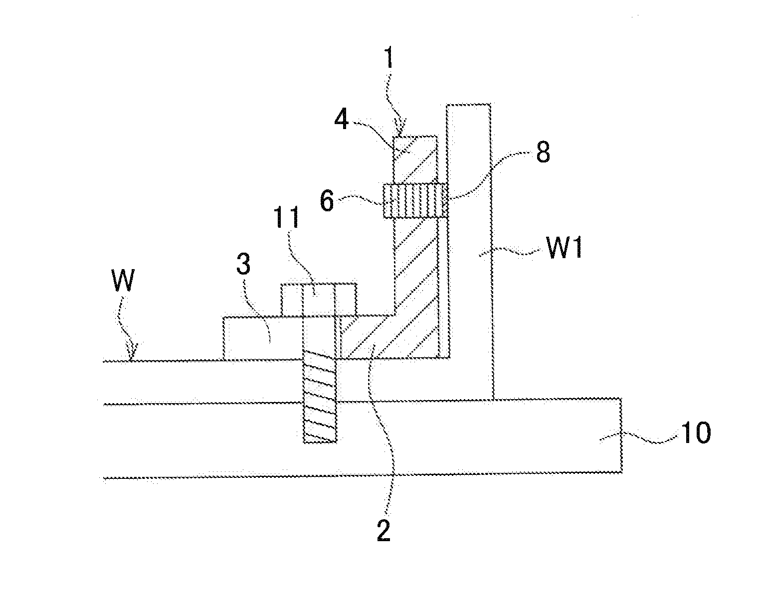
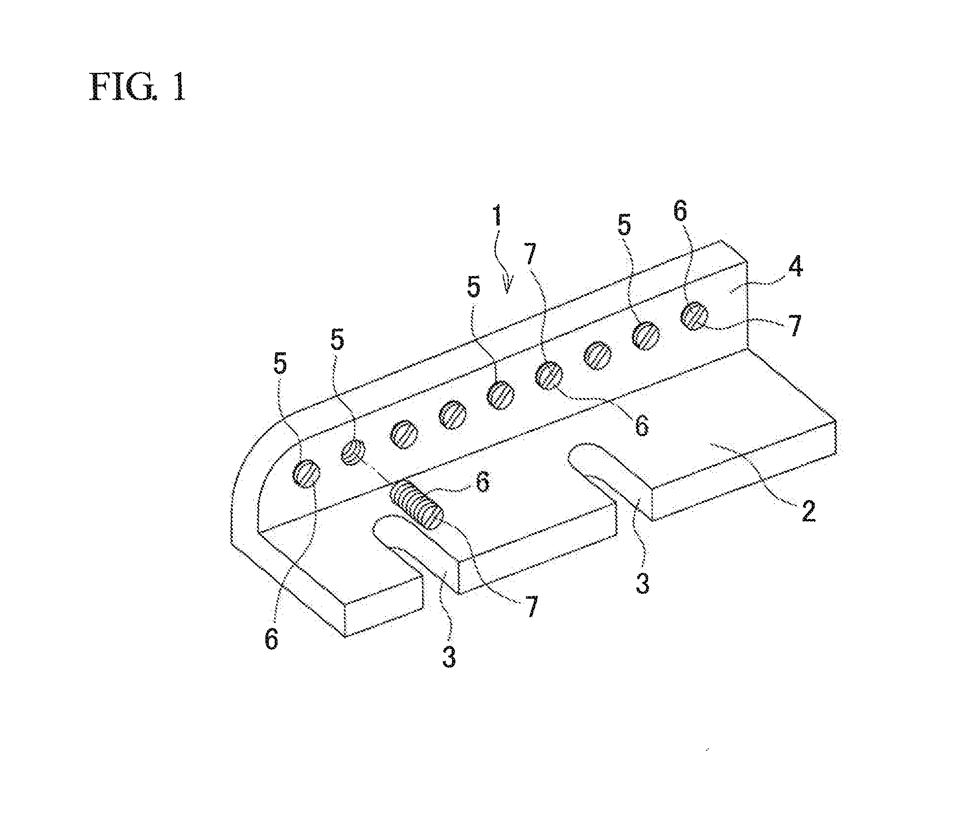
[0017]FIG. 1 is a perspective view illustrating an example of a chattering vibration preventing jig for workpiece. The chattering vibration preventing jig 1 is made of metal, and is L-shaped as viewed from the side. A horizontal plate portion 2 has a pair of cuts 3 extending in the short-side direction from an end of the horizontal plate portion 2. A vertical plate portion 4 has a plurality of screw holes 5 arranged in a line in the long-side direction. Screws 6 slightly longer than lengths of the screw holes 5 are screwed into the corresponding screw holes 5. At least one groove 7 is formed in one end surface of each of the screws 6 and configured to catch a tip of a screwdriver or the like.

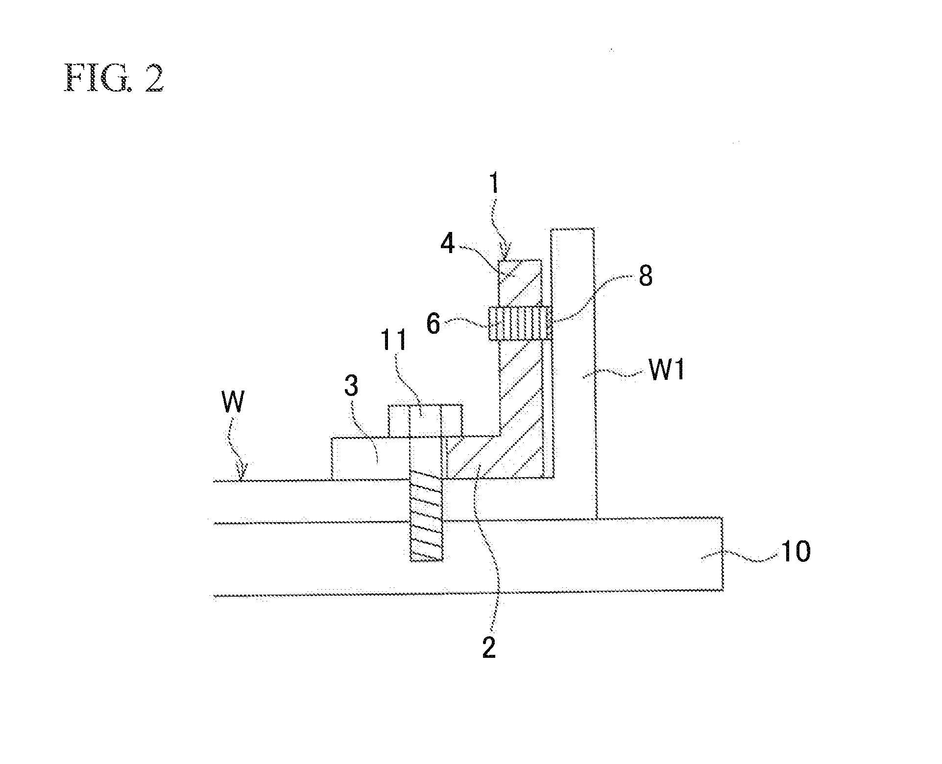
[0018]The chattering vibration preventing jig 1 thus constructed is attached to a workpiece W fixed to a base jig 10 in a manner illustrated in FIG. 2, for example. The base jig 10 is provided ...


PUM

PropertyMeasurementUnit
forceaaaaaaaaaa
shapeaaaaaaaaaa
lengthsaaaaaaaaaa

Abstract

A chattering vibration preventing jig is made of metal, and is L-shaped as viewed from the side. A horizontal plate portion has a pair of cuts extending in the short-side direction from an end of the horizontal plate portion. A vertical plate portion has a plurality of screw holes arranged in a line in the long-side direction. Screws slightly longer than lengths of the screw holes are screwed into the corresponding screw holes to abut onto a workpiece. Adhesive is applied to abutment surfaces of the screws that abut onto the workpiece.

Description

BACKGROUND OF THE INVENTION[0001]This application claims the benefit of Japanese Patent Application Number 2013-233323 filed on Nov. 11, 2013, the entirety of which is incorporated by reference.TECHNICAL FIELD[0002]The present invention relates to a chattering vibration preventing jig for workpiece for preventing chattering vibration generated in a workpiece during machining of the workpiece by a machine tool.BACKGROUND ART[0003]During machining of a workpiece by a machine tool, chattering vibration is generated in the workpiece in some cases since a force produced by a tool acts on the workpiece. To avoid generation of the chattering vibration, one of possible methods may be easing of machining conditions. Since the method may decrease the machining efficiency, however, an alternative method is employed in which a chattering vibration preventing jig is used as disclosed in Japanese Patent Application Publication No. 2008-87138, for example. According to the disclosure, a chattering...

Claims


Application Information

Patent Timeline
Patent Type & Authority Applications(United States)
IPC IPC(8): B23Q3/08
CPCB23Q3/084B23C2250/16B23Q11/0032B23Q17/0976Y10T409/304312
Inventor FUKUDA, YOSHITAKASUZUKI, RYO
Owner OKUMA CORP
Learn More