
Wireless power transfer method, apparatus and system

a power transfer method and wireless technology, applied in the direction of exchanging data chargers, inductances, transportation and packaging, etc., can solve the problem of limiting the charging distance between the magnetic induction method and the receiver, and achieve the effect of increasing the charging distance and increasing the degree of freedom

Inactive Publication Date: 2015-05-14
LG ELECTRONICS INC
View PDF12 Cites 31 Cited by
  • Summary
  • Abstract
  • Description
  • Claims
  • Application Information

AI Technical Summary

Benefits of technology

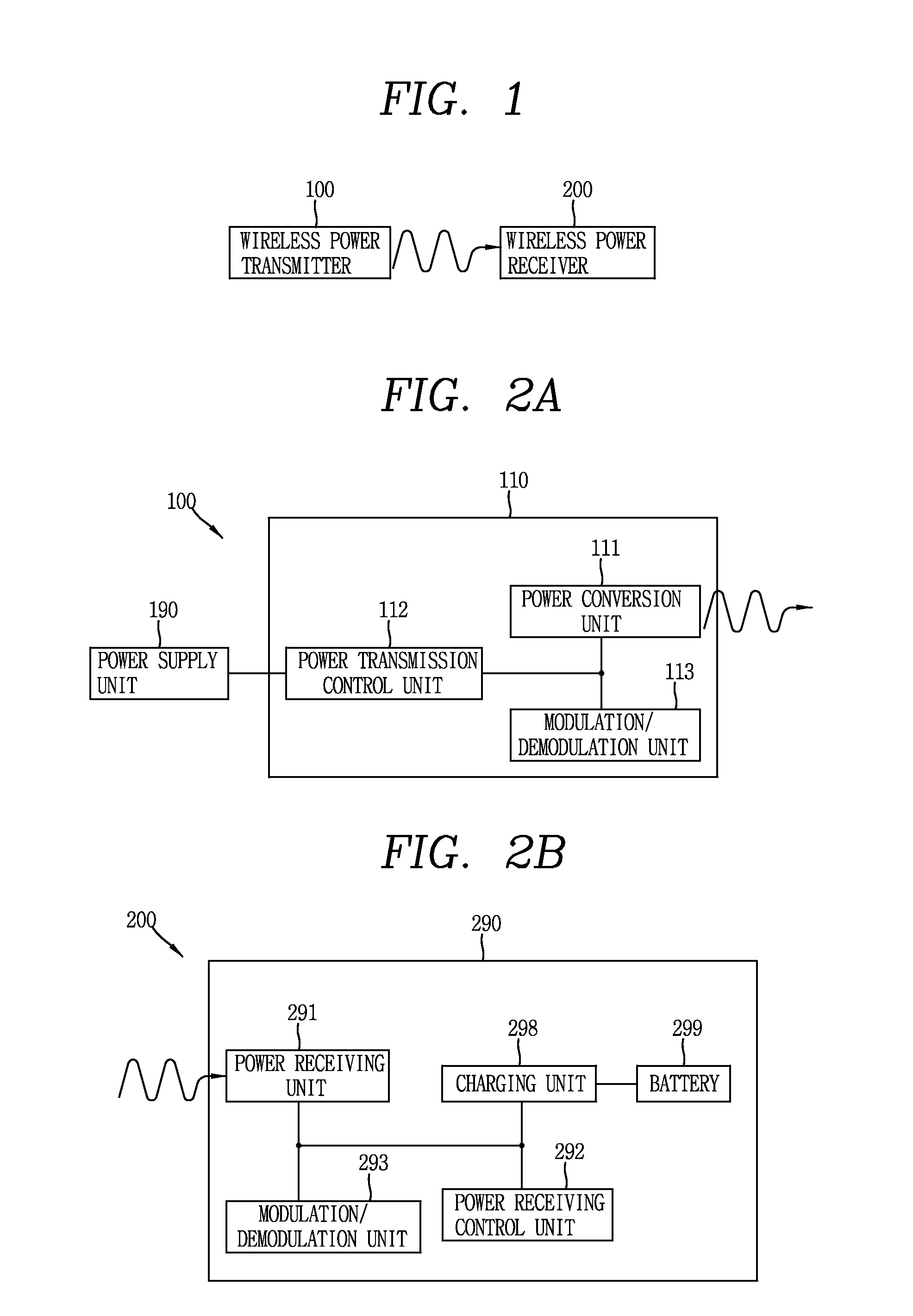
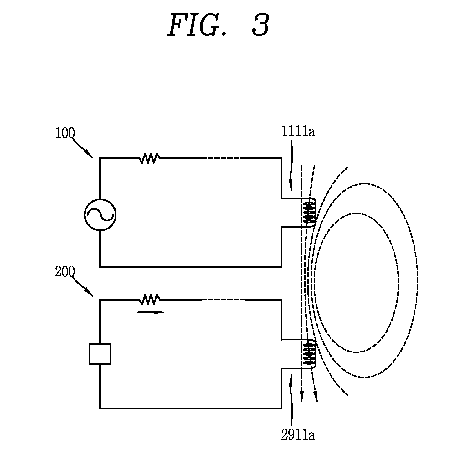
The present patent text describes a mechanism for increasing the charging distance in wireless power transmitters and charging systems. This is achieved by using a repeater that can overcome the limitation of charging only when the transmitter and receiver are placed at a limited position during magnetic induction. The repeater also increases the degree of freedom from the charging perspective. Additionally, the text describes an induction / resonance-compatible coil that combines an induction-type coil and a resonance-type coil to provide a technology for developing an already-commercialized induction method into a resonance method.

Problems solved by technology

However, the magnetic induction method has a limitation in a charging distance between a coil and a receiver.

Method used


Image

  • Wireless power transfer method, apparatus and system
  • Wireless power transfer method, apparatus and system
  • Wireless power transfer method, apparatus and system

Examples


Embodiment Construction

[0052]The technologies disclosed herein may be applicable to wireless power transfer (or wireless power transmission). However, the technologies disclosed herein are not limited to this, and may be also applicable to all kinds of power transmission systems and methods, wireless charging circuits and methods to which the technological spirit of the technology can be applicable, in addition to the methods and apparatuses using power transmitted in a wireless manner.

[0053]It should be noted that technological terms used herein are merely used to describe a specific embodiment, but not to limit the present invention. Also, unless particularly defined otherwise, technological terms used herein should be construed as a meaning that is generally understood by those having ordinary skill in the art to which the invention pertains, and should not be construed too broadly or too narrowly. Furthermore, if technological terms used herein are wrong terms unable to correctly express the spirit of...


PUM


Abstract

The present disclosure provides a wireless power transmitter, which is configured to transmit power to a wireless power receiver in a wireless manner. The wireless power transmitter includes a main body that is provided with a transmitting coil configured to transform a magnetic flux through a current change to transmit the wireless power, and a repeater that is provided with a repeating coil configured to receive the wireless power based on the magnetic flux transformation and transfer the received wireless power to the wireless power receiver, wherein the repeating coil faces the transmitting coil.

Description

CROSS-REFERENCE TO RELATED APPLICATION[0001]Pursuant to 35 U.S.C. §119(a), this application claims the benefit of earlier filing date and right of priority to U.S. Provisional Application No. 61 / 894,718, filed on Oct. 23, 2013, and Korean Patent Application No. 10-2014-0096685, filed on Jul. 29, 2014, the contents of which are incorporated by reference herein in their entireties.BACKGROUND OF THE DISCLOSURE[0002]1. Field of the Disclosure[0003]This specification relates to a wireless power transfer method, apparatus and system in a wireless power transfer field.[0004]2. Background of the Disclosure[0005]In recent years, the method of contactlessly supplying electrical energy to wireless power receivers in a wireless manner has been used instead of the traditional method of supplying electrical energy in a wired manner. The wireless power receiver receiving energy in a wireless manner may be directly driven by the received wireless power, or a battery may be charged by using the rece...

Claims


Application Information

Patent Timeline
IPC IPC(8): H02J17/00H02J5/00H02J7/02
CPCH02J17/00H02J5/005H02J7/025H02J50/50H02J50/80H02J50/90H02J7/00034H02J50/12H02J50/70
Inventor LEE, SEONGHUNGWAK, BONGSIKSEO, JEONGKYO
Owner LG ELECTRONICS INC
Learn More