Diode load driving power supply apparatus

Active Publication Date: 2015-05-14
MURATA MFG CO LTD
View PDF3 Cites 12 Cited by
  • Summary
  • Abstract
  • Description
  • Claims
  • Application Information

AI Technical Summary

Benefits of technology

[0017]According to various preferred embodiments of the present invention, start up variations such as an overshoot generated in the rise of a current flowing through

Problems solved by technology

When a plurality of diode loads are controlled in a unified manner using a single controller in a state where there are variations between their forward drop voltages VF, a problem occurs in that an overshoot or rise delay is generated in the current rise characteristics at the time of start up.
This is a problem that causes noise to be generated on the load side and affects the load-side characteristics when the LEDs are used as th

Method used


Image

  • Diode load driving power supply apparatus
  • Diode load driving power supply apparatus
  • Diode load driving power supply apparatus

Examples


embodiment 1

Preferred Embodiment 1

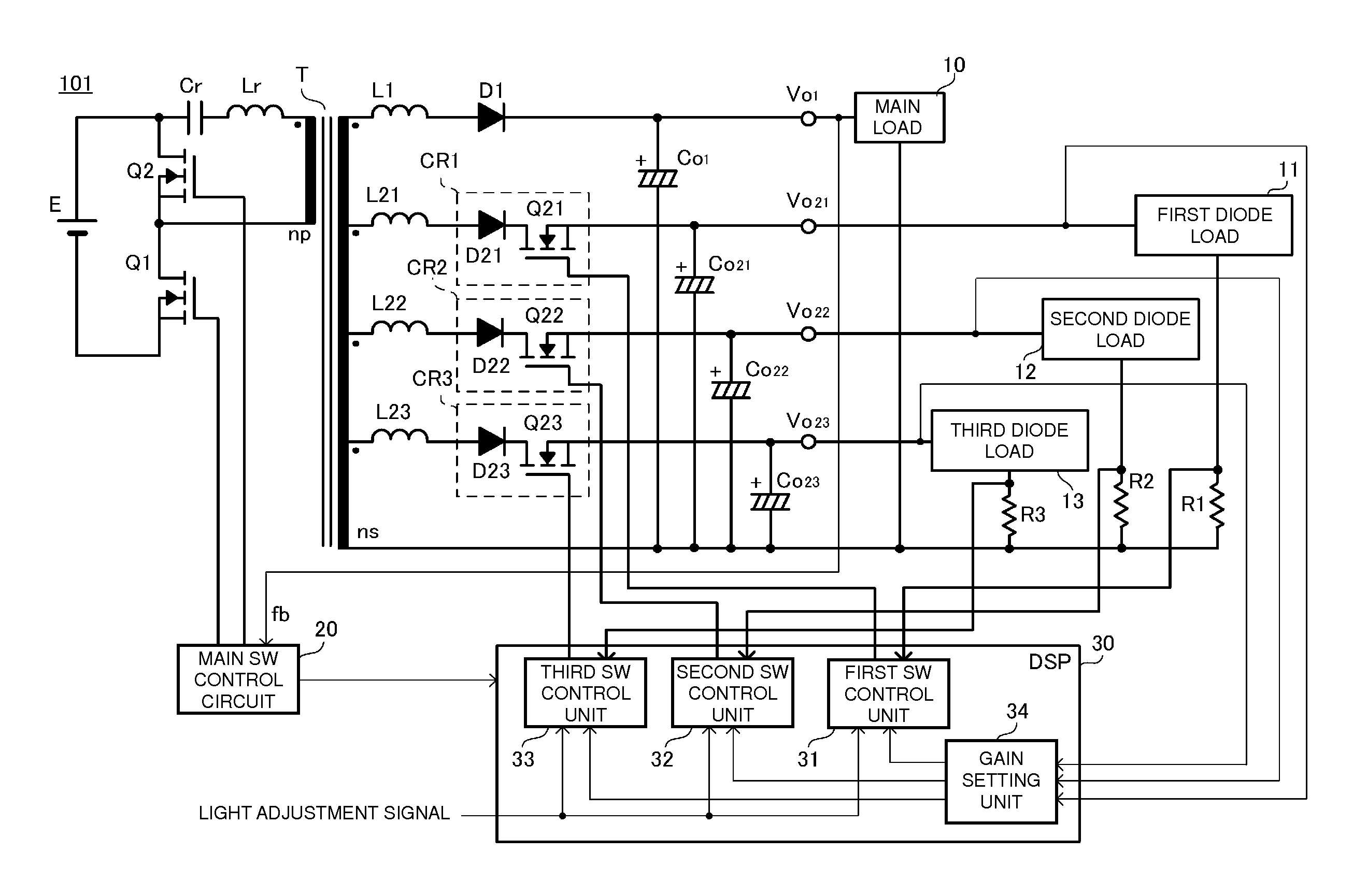
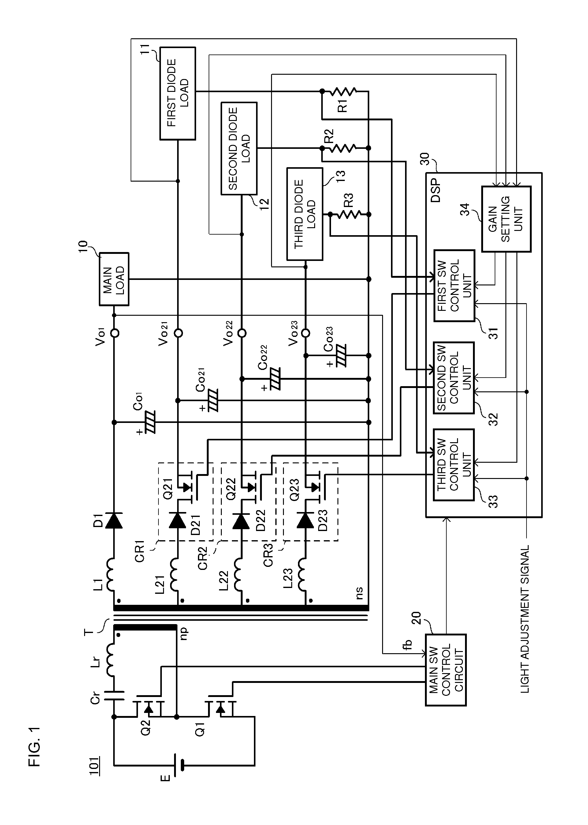
[0027]FIG. 1 is a circuit diagram of a diode load driving power supply apparatus according to preferred embodiment 1 of the present invention. A diode load driving power supply apparatus 101 according to this preferred embodiment includes a transformer T equipped with a primary winding np and a secondary winding ns. The diode load driving power supply apparatus 101 is equipped with an input power supply E on the primary side of the transformer T and is equipped with a main load 10, a first diode load 11, a second diode load 12 and a third diode load 13 on the secondary side of the transformer T.

[0028]A low-side switch element Q1 is connected in series with the primary winding np. In addition, a high-side switch element Q2, a resonance capacitor Cr and inductor Lr are connected to the primary winding np and define a closed loop. The circuit defined by the low-side switch element Q1, the high-side switch element Q2 and so on causes a current to flow forwards and ...

embodiment 2

Preferred Embodiment 2

[0063]FIG. 6 is a circuit diagram of a diode load driving power supply apparatus according to preferred embodiment 2 of the present invention. The diode load driving power supply apparatus 101 according to preferred embodiment 1 preferably sets a corresponding feedback gain for every read forward drop voltage VF. In contrast, a diode load driving power supply apparatus 102 according to this preferred embodiment preferably compares the read forward drop voltages VF and allocates smaller feedback gains as the forward drop voltages VF decrease.

[0064]In addition, the secondary side of the transformer T of the diode load driving power supply apparatus 102 according to this preferred embodiment is different from that of the diode load driving power supply apparatus 101 according to preferred embodiment 1. Hereafter, the circuit configuration of the secondary side of the transformer T will be described. Components that are the same as those in preferred embodiment 1 w...

embodiment 3

Preferred Embodiment 3

[0077]FIG. 7 is a circuit diagram of a diode load driving power supply apparatus according to preferred embodiment 3 of the present invention. A diode load driving power supply apparatus 103 according to this preferred embodiment differs from those of preferred embodiments 1 and 2 in that it is not equipped with a transformer T and is equipped with a step down converter. This difference will be described below.

[0078]The diode load driving power supply apparatus 103 is equipped with a first rectifying / smoothing circuit, a second rectifying / smoothing circuit and a third rectifying / smoothing circuit connected to an input power supply E.

[0079]The first rectifying / smoothing circuit includes a first switching circuit CR31 and a smoothing capacitor Co31. The first switching circuit CR31 is a step down converter circuit that includes a switch element Q31, a diode D31 and an inductor L31. The first rectifying / smoothing circuit switches and then rectifies and smoothes th...


PUM


Abstract

A main rectifying/smoothing circuit is connected to one end of a secondary winding of a transformer and a plurality of rectifying/smoothing circuits are connected to a plurality of central taps of the secondary winding. The rectifying/smoothing circuits are each equipped with a switch. In a preliminary driving period, a DSP, which controls the switches, reads forward drop voltages of first to third diode loads and sets feedback gains corresponding to the forward drop voltages. The DSP controls the switches based on the set feedback gains and begins rated driving.

Description

BACKGROUND OF THE INVENTION[0001]1. Field of the Invention[0002]The present invention relates to a diode load driving power supply apparatus that supplies power to a plurality of diode loads in order to drive the diode loads.[0003]2. Description of the Related Art[0004]In Japanese Unexamined Patent Application Publication No. 2011-124195, there is disclosed a lighting circuit that lights a plurality of LEDs. The circuit described in Japanese Unexamined Patent Application Publication No. 2011-124195 has a configuration in which a DC-DC converter is provided for each of the plurality of LEDs. It is described that, with this configuration, a stable current is supplied to each of the LEDs and therefore lighting of the LEDs can be accurately controlled and the LEDs can be prevented from flickering, for example.[0005]When a plurality of diode loads are controlled in a unified manner using a single controller in a state where there are variations between their forward drop voltages VF, a p...

Claims


Application Information

Patent Timeline
IPC IPC(8): G05F1/614G05F1/46H05B44/00
CPCG05F1/467G05F1/614H02M3/33561Y02B20/30H05B45/382H05B45/375
Inventor ASAI, HIROTSUGUMATSUMOTO, HIRONORI
Owner MURATA MFG CO LTD
Why Eureka
Try Eureka