Hydrogen tank body and method of producing the same, and hydrogen tank and method of producing the same

a technology of hydrogen tank and body, which is applied in the direction of electrochemical generators, container discharging methods, other domestic articles, etc., can solve the problems of unnecessary dimensions and variations in dimensions when the hydrogen tank body is formed, and achieve the effect of reducing or preventing the variation in the dimensions of the hydrogen tank body

Active Publication Date: 2021-05-04
TOYOTA JIDOSHA KK
View PDF12 Cites 0 Cited by
  • Summary
  • Abstract
  • Description
  • Claims
  • Application Information

AI Technical Summary

Benefits of technology

[0004]However, the hydrogen tank body formed of a polyamide resin composition is likely to cause variations in dimensions during molding, due to processing characteristics of the polyamide resin composition. Accordingly, a technology for reducing or preventing variations in the dimensions of the hydrogen tank body has been desired.
[0005]The disclosure provides a technology for reducing or preventing variations in dimensions of a hydrogen tank body.

Problems solved by technology

However, the hydrogen tank body formed of a polyamide resin composition is likely to cause variations in dimensions during molding, due to processing characteristics of the polyamide resin composition.
Since the base layer of the hydrogen tank body is formed by injection molding, welding that would cause variations in dimensions when the hydrogen tank body is formed may be unnecessary.

Method used


Image

  • Hydrogen tank body and method of producing the same, and hydrogen tank and method of producing the same
  • Hydrogen tank body and method of producing the same, and hydrogen tank and method of producing the same
  • Hydrogen tank body and method of producing the same, and hydrogen tank and method of producing the same

Examples


first embodiment

A. First Embodiment

A1. Configuration of Hydrogen Tank

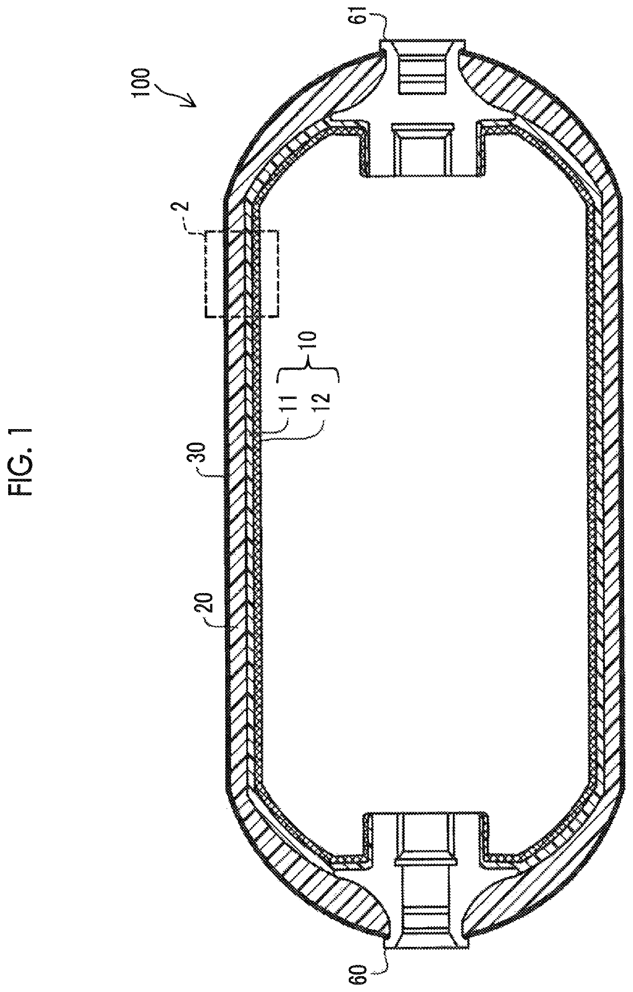
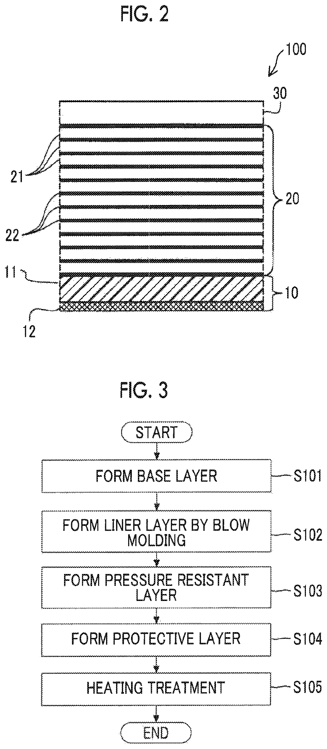
[0028]FIG. 1 schematically shows a hydrogen tank 100 according to a first embodiment. The hydrogen tank 100 includes a hydrogen tank body 10, a pressure resistant layer 20, a protective layer 30, a first cap 60, and a second cap 61. The hydrogen tank 100 is constructed such that the hydrogen tank body 10 having a hollow interior is covered with the pressure resistant layer 20 and the protective layer 30. The first cap 60 and the second cap 61 are respectively disposed at longitudinally opposite ends of the hydrogen tank body 10. The hydrogen tank 100 is filled with compressed hydrogen, and is installed on a fuel cell vehicle so as to supply hydrogen to a fuel cell, for example. The hydrogen tank 100 is not limitedly installed on the fuel cell vehicle, but may be installed in a mobile object, such as a ship or an airplane, or a stationary facility, such as a house or a building.

[0029]The hydrogen tank body 10 is a hollow container ...

second embodiment

B. Second Embodiment

[0056]A second embodiment is different from the first embodiment in that the base layer 11 is divided into two or more parts and formed, in the process for production of the hydrogen tank body 10. After the base layer 11 is divided and formed, hydrogen impermeable resin is applied by coating to an inside wall surface of the base layer 11, so as to form the liner layer 12. The base layer 11 thus divided and formed and the liner layer 12 are welded together, so that the hydrogen tank body 10 is formed. In other aspects of the configuration and production method, the second embodiment is substantially identical with the first embodiment. Although welding is performed in formation of the hydrogen tank body 10 in the second embodiment, it is possible to reduce variations in dimensions as compared with the hydrogen tank body 70 of the comparative example, since silicon resin having higher strength than polyamide 6 is used for the base layer 11. Since the liner layer 12...


PUM

PropertyMeasurementUnit
thicknessaaaaaaaaaa
thicknessaaaaaaaaaa
thicknessaaaaaaaaaa

Abstract

A hydrogen tank body includes a base layer formed of a synthetic resin selected from the group consisting of silicon resin, polyphenylene sulfide, polybutylene terephthalate, polyvinyl chloride, polypropylene, polyethylene, and polycarbonate, and a liner layer formed of hydrogen impermeable resin, on an inside wall surface of the base layer.

Description

INCORPORATION BY REFERENCE[0001]The disclosure of Japanese Patent Application No. 2017-029558 filed on Feb. 21, 2017 including the specification, drawings and abstract is incorporated herein by reference in its entirety.BACKGROUND1. Technical Field[0002]The disclosure relates to a hydrogen tank body, a method of producing the hydrogen tank body, a hydrogen tank, and a method of producing the hydrogen tank.2. Description of Related Art[0003]A hydrogen tank body formed of a polyamide resin composition having excellent hydrogen impermeability is known (see Japanese Patent Application Publication No. 2009-191871 (JP 2009-191871 A), for example). The hydrogen tank body functions as a liner layer in a hydrogen tank.SUMMARY[0004]However, the hydrogen tank body formed of a polyamide resin composition is likely to cause variations in dimensions during molding, due to processing characteristics of the polyamide resin composition. Accordingly, a technology for reducing or preventing variations...

Claims


Application Information

Patent Timeline
Patent Type & Authority Patents(United States)
IPC IPC(8): B29C69/00F17C1/16F17C13/06F17C1/06B29C49/20B29L9/00B29K77/00B29K83/00B29L31/00B29C49/24
CPCF17C1/16B29C49/20B29C69/007F17C1/06F17C13/06B29C2049/2404B29K2077/00B29K2083/00B29K2995/0067B29L2009/00B29L2031/7156F17C2201/0109F17C2201/056F17C2203/012F17C2203/0604F17C2203/066F17C2203/0607F17C2203/0624F17C2203/0663F17C2203/0675F17C2203/0685F17C2205/0305F17C2205/0397F17C2209/2127F17C2209/2154F17C2209/221F17C2209/232F17C2221/012F17C2223/0123F17C2223/036F17C2227/0381F17C2260/018F17C2270/0168F17C2270/0184Y02E60/32
Inventor IMAI, KATSUKI
Owner TOYOTA JIDOSHA KK
Why Eureka
Try Eureka