Liquid-crystal display device and method for driving same

Inactive Publication Date: 2015-05-14
SHARP KK
View PDF4 Cites 2 Cited by
  • Summary
  • Abstract
  • Description
  • Claims
  • Application Information

AI Technical Summary

Benefits of technology

[0023]According to the first aspect of the invention, in a liquid crystal display device that can perform three dimensional display by the frame sequential method, a black image is written during the vertical blanking period of each frame period. As a result, in a case in which the difference in gradation level is large between the left eye image and the right eye image, writing of a low gradation image in the liquid crystal panel occurs twice in one frame period. As a result, when the writing of an image takes place for an image with low gradation, the gradation level reached can be sufficiently lowered. Thus, unlike before, an image having excess gradation is not perceived. Thus, a liquid crystal display device that can perform three-dimensional display by which it is possible to suppress the decrease in image quality due to crosstalk when the difference in the gradation level between the right eye image and the left eye image is large is realized.
[0024]According to the second aspect of the present invention, the black image is kept in the line for displaying the left eye image during the period when writing of the right eye image occurs, and the black image is kept in the line for displaying the right eye image during the period when writing of the left eye image occurs. Thus, the period during which the black image is held at each pixel is long, and thus, the gradation level is reliably and sufficiently low during the period in which the black i

Problems solved by technology

Reducing crosstalk has been a problem for liquid crystal d

Method used


Image

  • Liquid-crystal display device and method for driving same
  • Liquid-crystal display device and method for driving same
  • Liquid-crystal display device and method for driving same

Examples


Example

1. Embodiment 1

1.1 Overall Configuration and Summary of Operation

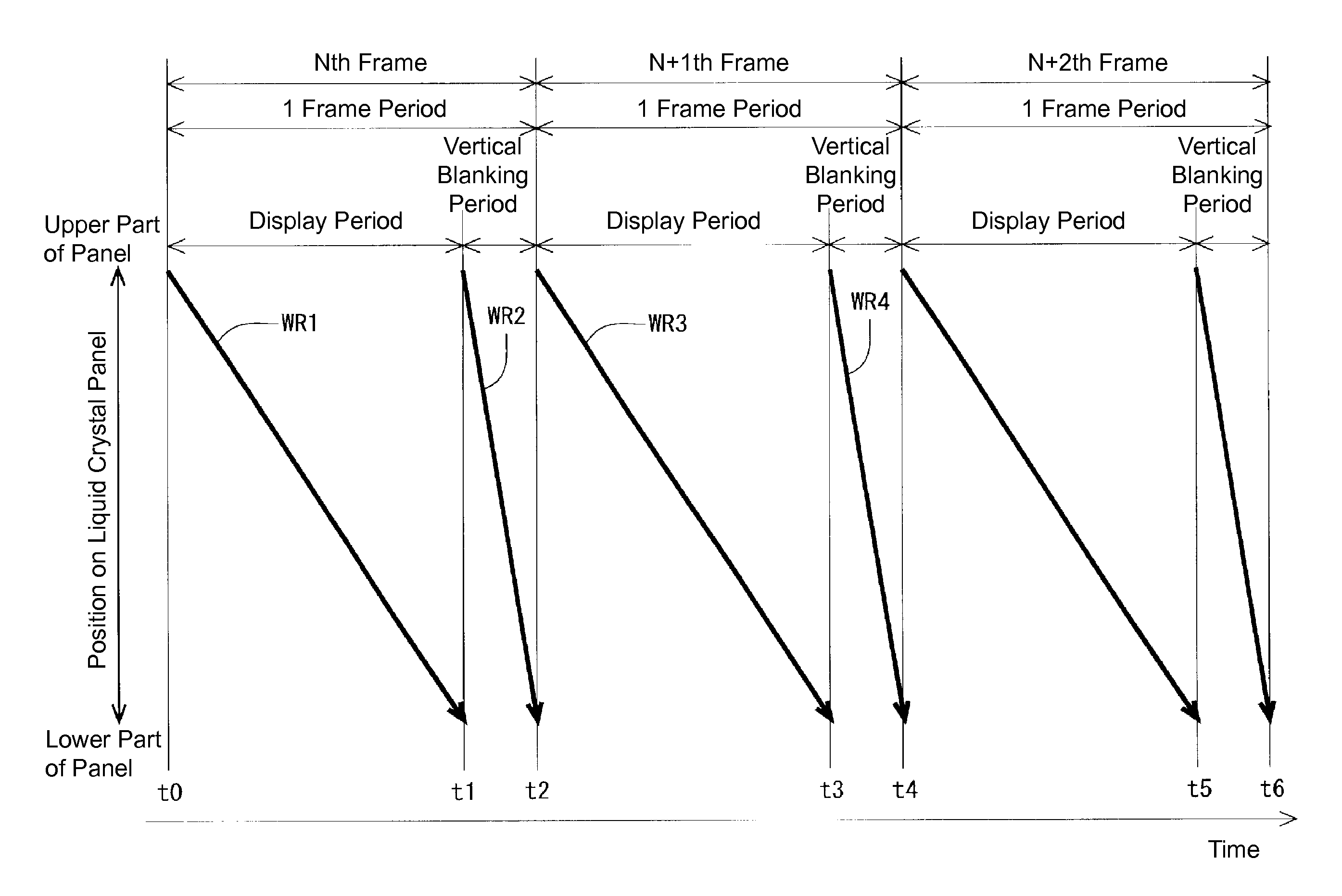
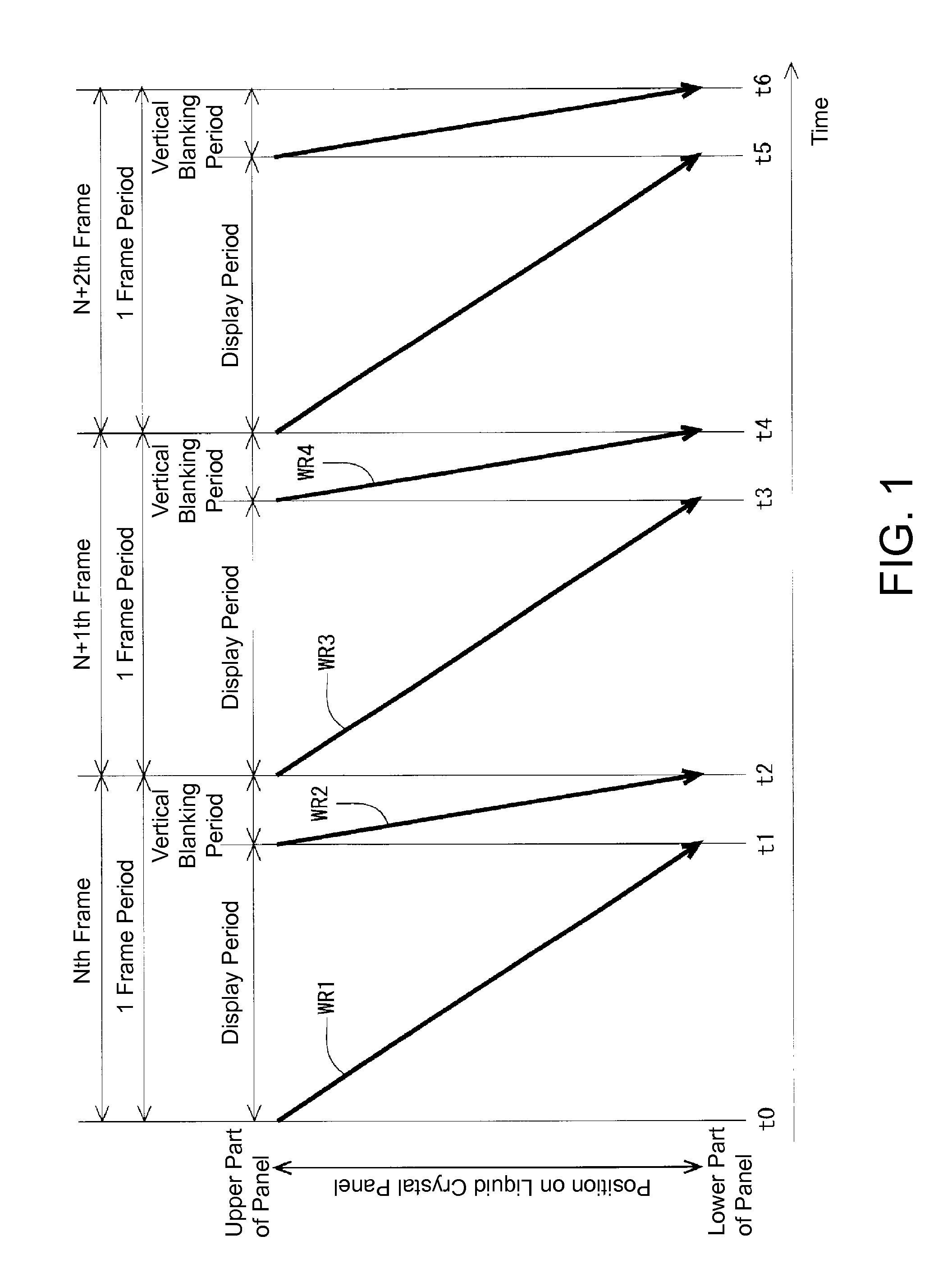
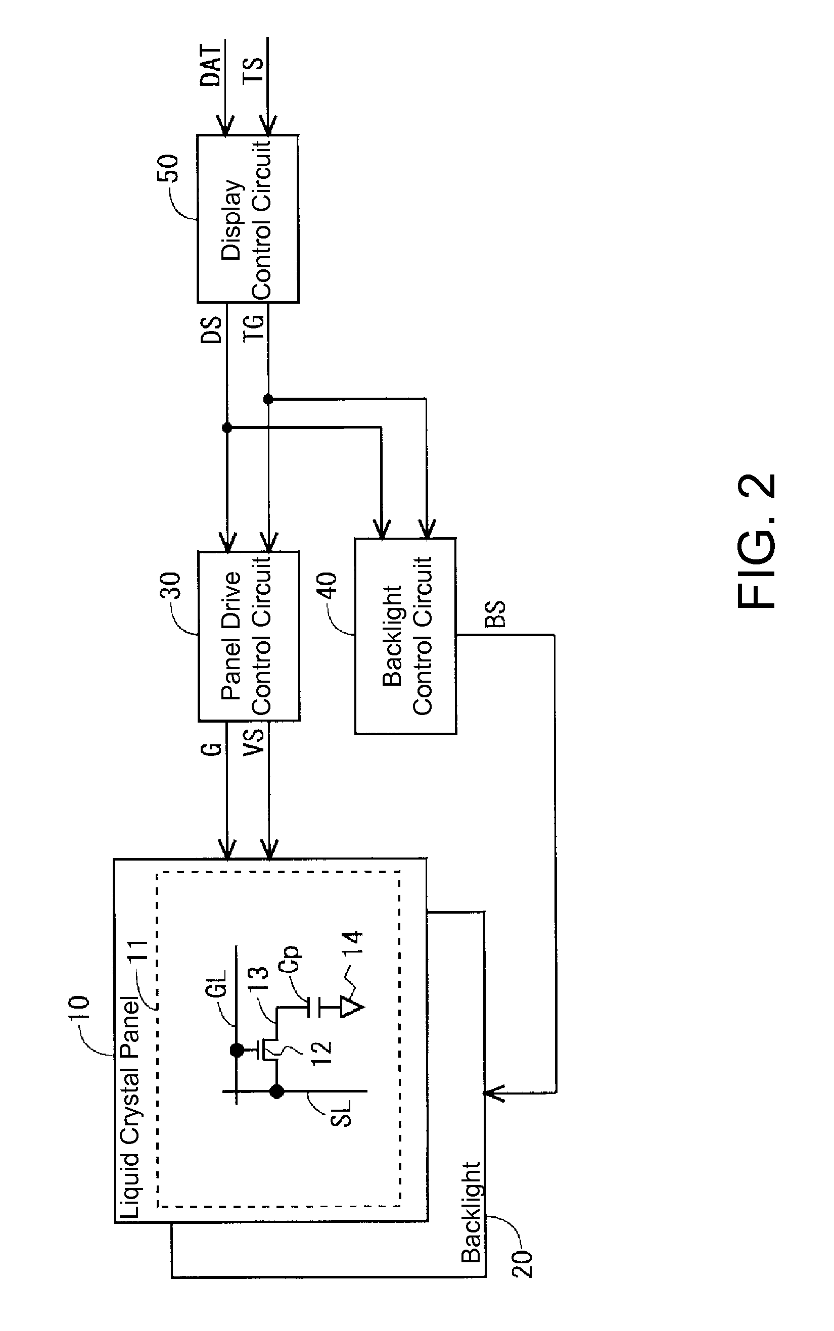
[0051]FIG. 2 is a block diagram showing a configuration of a liquid crystal display device according to Embodiment 1 of the present invention. This liquid crystal display device has a liquid crystal panel 10, a backlight 20, a panel drive control circuit (liquid crystal panel driving unit) 30, a backlight control circuit (light source control unit) 40, and a display control circuit 50. The liquid crystal display device is configured such that three dimensional display (stereoscopic vision) can be performed. As a method of attaining three dimensional display, the frame sequential method by which a left eye image and a right eye image are alternately displayed is adopted. Typically, so called double speed driving and quadruple speed driving is adopted.

[0052]The liquid crystal panel 10 includes a display unit 11. The display unit 11 is provided with a plurality of image signal lines SL and a plurality of scan signal line...

Example

2. Embodiment 2

2.1 Configuration and the Like

[0064]Next, Embodiment 2 of the present invention will be described. The overall configuration and configuration of the display control circuit 50 are similar to those of Embodiment 1 (see FIGS. 2 to 5), and thus, descriptions thereof are omitted. However, in the present embodiment, the interlace driving method is adopted. Therefore, if one frame period is 1 / 120 of a second, then a digital image signal DS for even lines during a frame period is outputted from the display control circuit 50, and during the next frame period, a digital image signal DS for odd lines is outputted from the display control circuit 50. Then, the right eye image is written when the even numbered scan signal lines GL among the plurality of scan signal lines GL disposed in the display unit 11 are scanned, and the left eye image is written when the odd numbered scan signal lines GL among the plurality of scan signal lines GL are scanned. By writing the right eye i...


PUM


Abstract

An objective of the present invention is to implement a liquid crystal display device which is capable of a three dimensional display, with which it is possible to alleviate image quality degradation caused by crosstalk when a difference in gradation between a left eye image and a right eye image is large. Provided is a liquid-crystal display device that is capable of a three dimensional display, in which a panel drive control circuit alternately performs writing of a right-eye image and writing of a left-eye image for each frame period in order from one end to another end of a liquid crystal panel, and performs writing of either a near-black image or a black image in order from the one end to the other end of the liquid crystal panel in a vertical blanking period during each of the frame periods.

Description

TECHNICAL FIELD [0001]The present invention relates to a liquid crystal display device, and in particular to a liquid crystal display device that can perform three dimensional display.BACKGROUND ART[0002]In recent years, many liquid crystal display devices that can display three dimensional images such as 3D televisions are being sold. In liquid crystal display devices that employ the field sequential method, which is one method of attaining three dimensional display, a left eye image and a right eye image are alternately displayed in a liquid crystal panel per prescribed period ( 1 / 120 of a second, for example), and lenses of active shutter 3D glasses alternately open and close in synchronization therewith. FIG. 19 is a schematic view showing the progression of image writing (here, writing refers to charging the pixel capacitance in a liquid crystal panel based on the image signal having the target potential) in respective locations of the liquid crystal panel of a conventional liq...

Claims


Application Information

Patent Timeline
IPC IPC(8): G09G3/34G09G3/36H04N13/04G02B27/22G02F1/1335
CPCG09G3/3406G02B27/2264G09G3/3611H04N13/0438H04N13/0497G02F1/133603G09G3/003G09G2320/0209G09G2320/0252G09G2340/16H04N13/341H04N13/398G02B30/24
Inventor MATSUMOTO, SHINJIKAWABATA, MASAEIRIE, KENTAROH
Owner SHARP KK
Why Eureka
Try Eureka