

Image display device and driving method of the same
- Summary
- Abstract
- Description
- Claims
- Application Information
AI Technical Summary
Benefits of technology
Problems solved by technology
Method used
Image

Examples
first embodiment
[0080]The following descriptions will explain one embodiment of the present invention with reference to drawings.
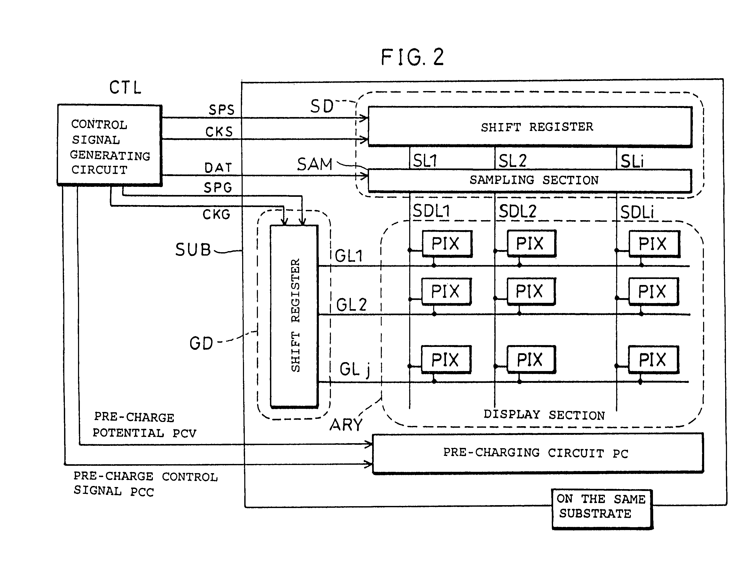
[0081]FIG. 2 is a block diagram illustrating a schematic structure of an image display device in accordance with the present embodiment. As shown in FIG. 2, the image display device includes a data signal line drive circuit SD, a scanning signal line drive circuit GD, a data signal line SDLn (1≦n≦i), the scanning signal line GLn (1≦n≦j), pixel PIX, a control signal generating circuit CTL, and a preliminary charging circuit PC. The structure of the pixel PIX section is shown in FIG. 12.
[0082]As shown in FIG. 12, the pixel PIX includes a switching element SW, a liquid crystal capacity CL and an auxiliary capacity CS. One end of the capacitance which constitutes the pixel PIX is connected to the data signal lines SDL via the switching circuit. The other end of the capacitance is connected to the common electrode called counter electrode COM. Namely, the potential difference ...
second embodiment
[0106]The following descriptions will describe another embodiment of the present invention in reference to figures.
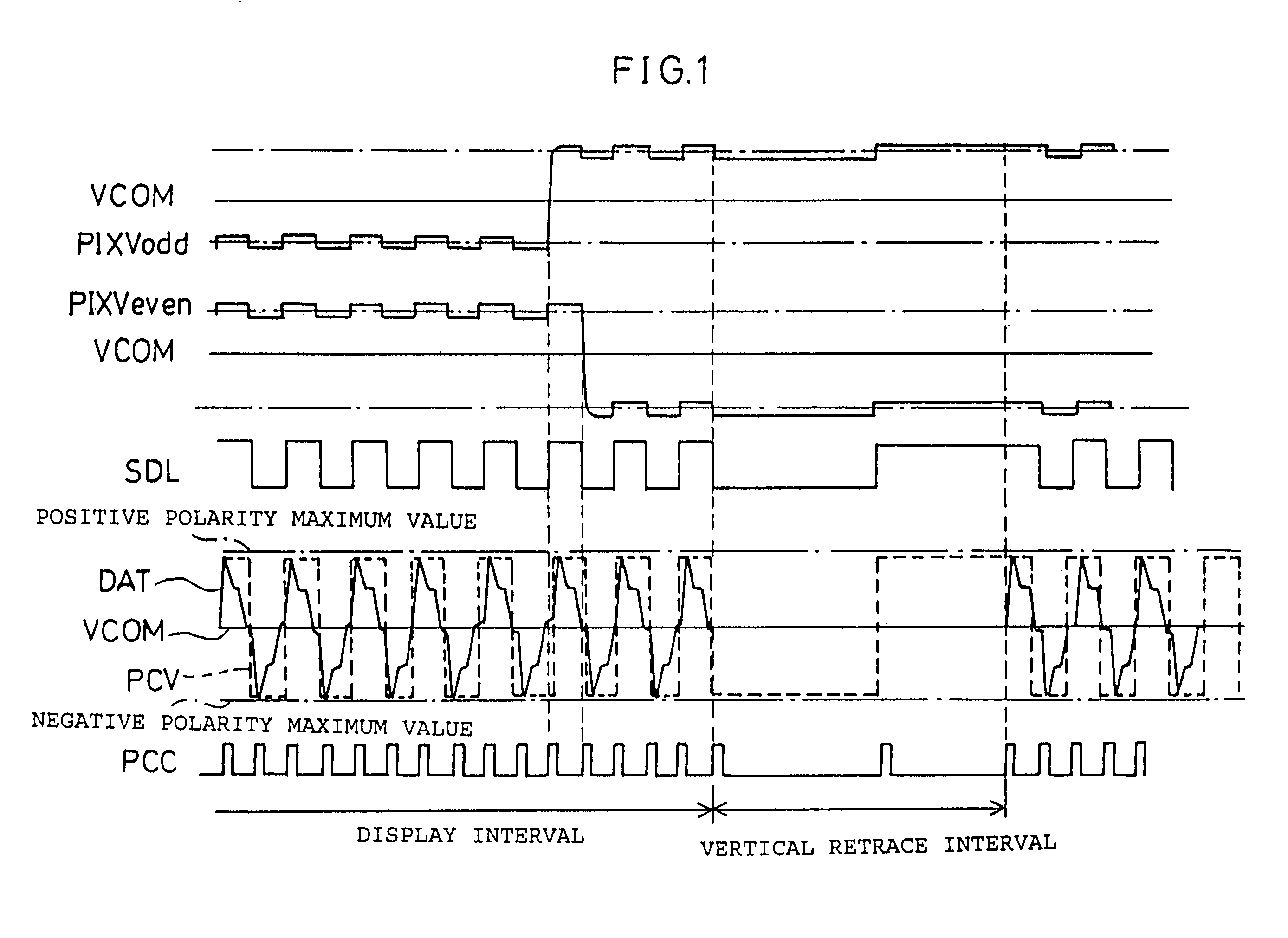
[0107]An image display device of the present embodiment has the same structure as that of the above-explained image display device of the first embodiment except that a pre-charge potential PCV has an AC potential in synchronization with 1 horizontal scan period (1H) of a video signal. A drive waveform of this embodiment is shown in FIG. 4.
[0108]The drive waveform shown in FIG. 4 only differs from that of the first embodiment only in AC period of the pre-charge potential PCV and a timing of the pre-charge control signal PCC, and a driving method and functions of members which constitute the image display device are the same as those of the first embodiment.
[0109]The structure of the present embodiment wherein a signal of a predetermined cycle in synchronization with 1 horizontal scan period (1H) is adopted for a signal of one kind, is preferable over the structure where...
third embodiment
[0116]The following descriptions will describe still another embodiment of the present invention in reference to figures.
[0117]The image display device of the present embodiment has the same basic structure as the first embodiment except for the following.
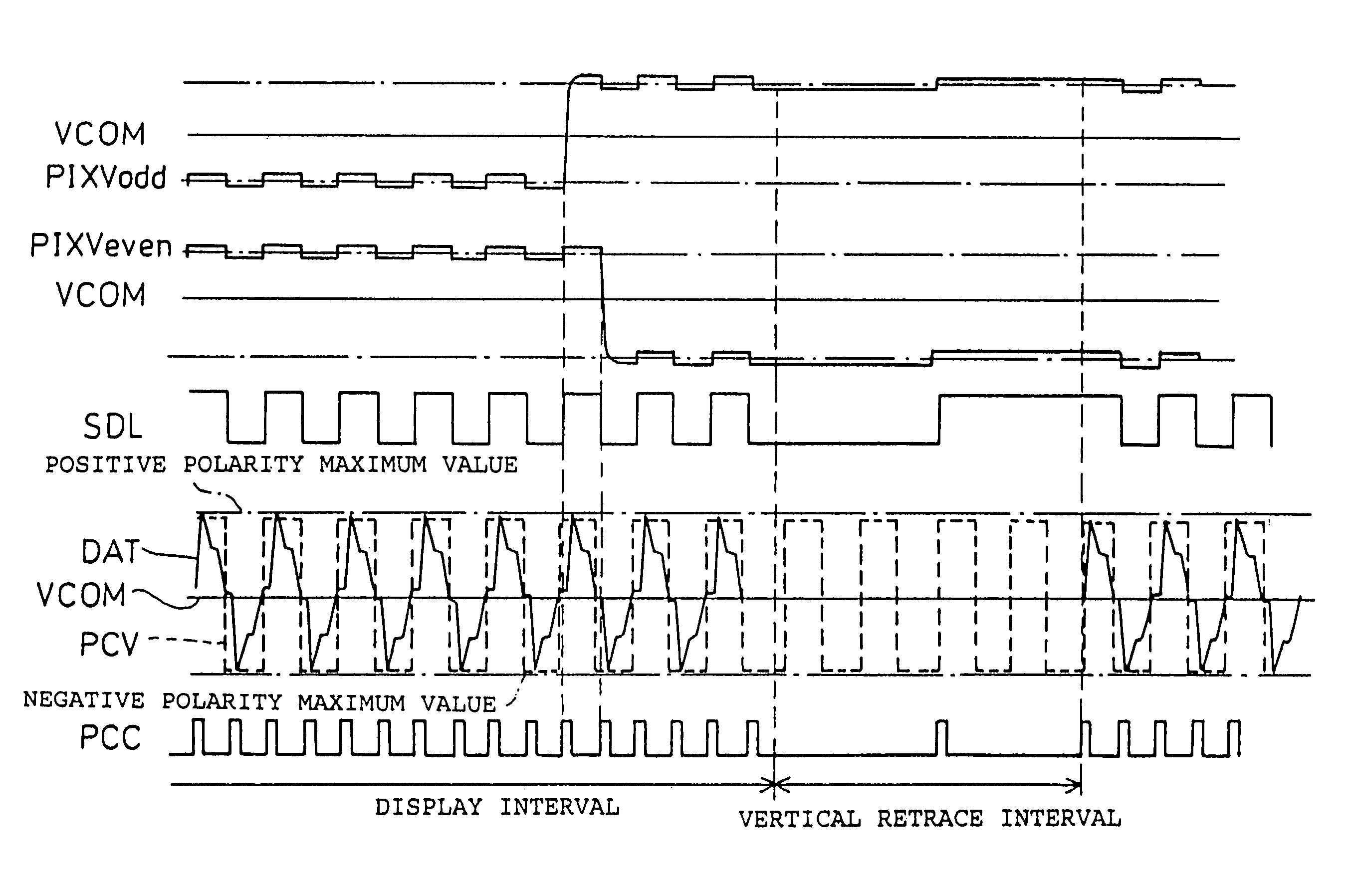
[0118]That is in the present embodiment, the pre-charge potential PCV in the vertical retrace interval is an AC potential of not less than 50 percent of the maximum value of the video signal of positive polarity, and not less than 50 percent of the maximum value of the video signal of negative polarity. The waveforms of respective members are as shown in FIG. 5.
[0119]The drive waveforms shown in FIG. 5 differ from those of the second embodiment only in the pre-charge potential PCV in the vertical retrace interval. The present embodiment has the same arrangement as the second embodiment in the driving method and functions of the members.
[0120]According to the arrangement of the present embodiment, a suitable potential of the pre-cha...
PUM
 Abstract
Description
Claims
Application Information