
Discontinuous reception dynamic configuration method, terminal and base station

a dynamic configuration and terminal technology, applied in the field of wireless communication technology, can solve the problems of not being able to adapt to other types of data business, not being able to optimize the power consumption of the terminal, and not being able to meet the needs of terminal power consumption optimization,

Inactive Publication Date: 2015-05-14
ZTE CORP
View PDF2 Cites 16 Cited by
  • Summary
  • Abstract
  • Description
  • Claims
  • Application Information

AI Technical Summary

Benefits of technology

The patent describes a method and device that can improve the efficiency of a network by dynamically configuring the timing of a terminal's power-saving cycle. This allows the network to better manage data services and meet the terminal's power needs, while the device itself can better balance energy consumption and performance. The method is easy to implement and flexible. Overall, this technology can make both networks and devices more efficient and effective.

Problems solved by technology

With the popularization of the intellectual mobile phone and the diversification of the intellectual software and application, the optimization demand on the terminal power consumption becomes a problem required to pay more and more attention to at present.
And also because the related technology cannot distinguish the instant communication business and other data business (except the speech business), if the number of times of configuration of the short DRX cycle is reduced simply, then it is possible that it is not adapted to other types of data business.
If the network dynamically adjusts the configuration of the short DRX cycle through measuring the data regular, it will cause extra signaling expenses of the RRC configuration, and influence the efficiency of the system.

Method used


Image

  • Discontinuous reception dynamic configuration method, terminal and base station
  • Discontinuous reception dynamic configuration method, terminal and base station
  • Discontinuous reception dynamic configuration method, terminal and base station

Examples


embodiment one

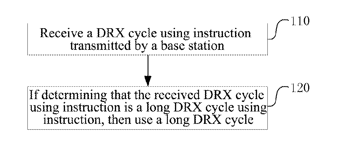
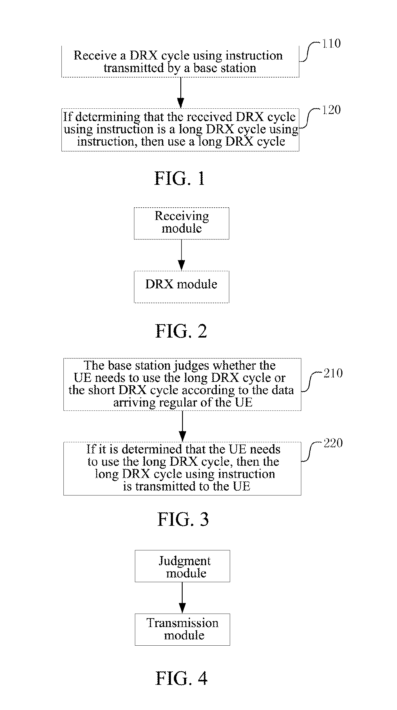
[0057]The present embodiment describes the processing executed by the terminal side in the method for dynamically configuring Discontinuous Reception (DRX), as shown in FIG. 1, including the following steps:

[0058]in step 110, a DRX cycle using instruction transmitted by a base station is received;

[0059]in step 120, if determining that the received DRX cycle using instruction is a long DRX cycle using instruction, then a long DRX cycle is used (for example, the long DRX cycle is statically used or dynamically used).

[0060]Preferably, if determining that the received DRX cycle using instruction is the short DRX cycle using instruction, then the UE uses the short DRX cycle.

[0061]The UE uses the long DRX cycle statically or uses the long DRX cycle dynamically according to the content of the long DRX cycle using instruction or according to an agreed configuration with a network side. If the content of the long DRX cycle using instruction indicates that the long DRX cycle using instruction...

embodiment two

[0082]The present embodiment describes a terminal for realizing the above-mentioned method, as shown in FIG. 3, including a receiving module and a DRX module, wherein:

[0083]the receiving module is configured to receive a DRX cycle using instruction transmitted by a base station; and

[0084]the DRX module is configured to: if determining that the DRX cycle using instruction received by the receiving module is a long DRX cycle using instruction, then use a long DRX cycle.

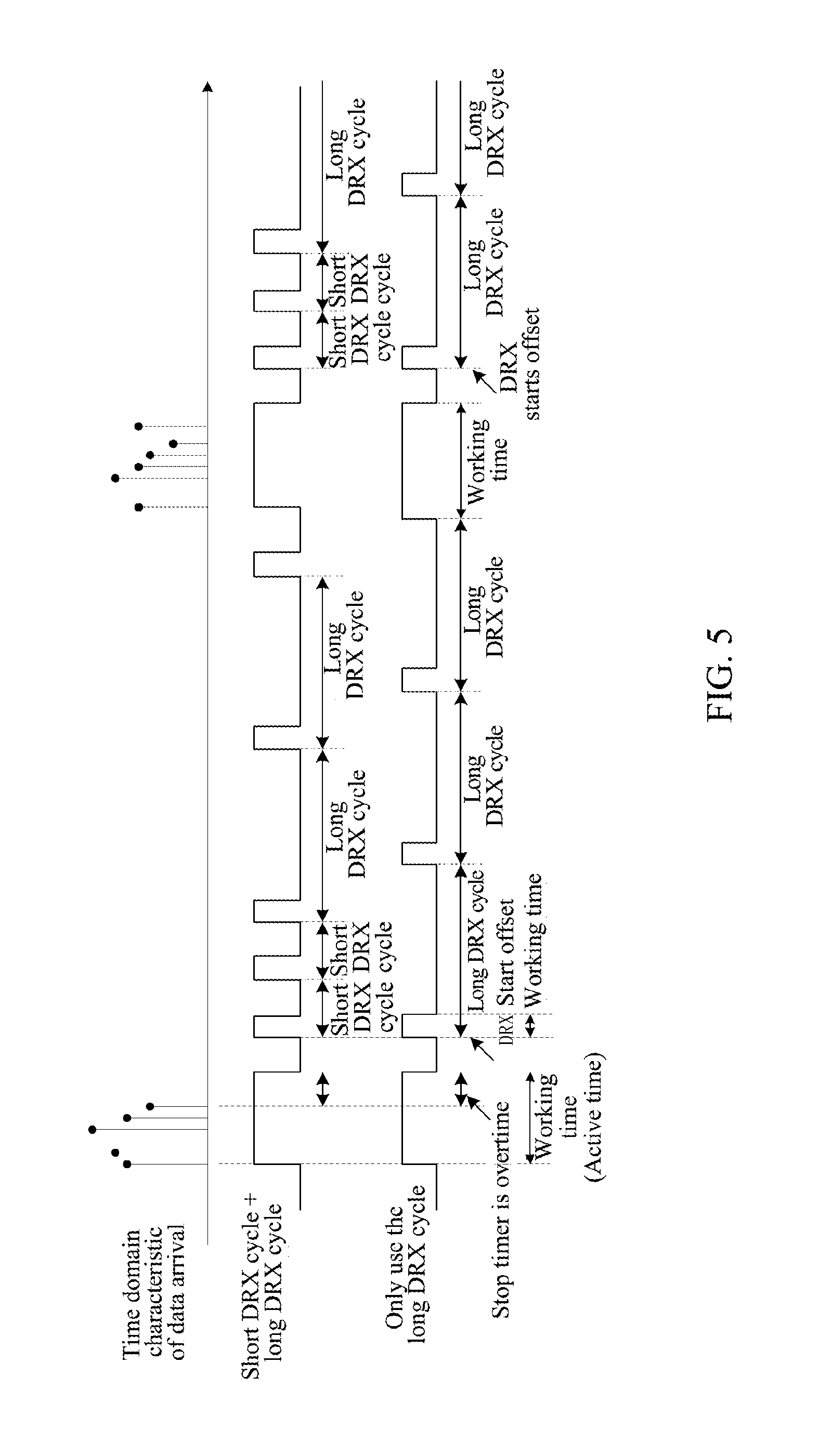
[0085]Preferably, the DRX module is configured to use the long DRX cycle by adopting the following way: using the long DRX cycle statically according to content of a long DRX cycle using instruction or according to an agreed configuration with a network side; wherein, the using the long DRX cycle statically refers to that the UE stops using a short DRX cycle and uses the long DRX cycle all the time.

[0086]If the current terminal is using the short DRX cycle when the receiving module receives the long DRX cycle using inst...

embodiment three

[0098]The present embodiment describes the processing executed by the base station side in the method for dynamically configuring Discontinuous Reception (DRX), as shown in FIG. 3, including the following steps:

[0099]in step 210, the base station judges whether the UE needs to use the long DRX cycle or the short DRX cycle according to the data arriving regular of the UE;

[0100]the data arriving regular includes frequency and / or interval of the arriving of data;

[0101]in step 220, if it is determined that the UE needs to use the long DRX cycle, then the long DRX cycle using instruction is transmitted to the UE.

[0102]Preferably, when the base station determines that the UE needs to use the short DRX cycle according to the data arriving regular of the UE, then the short DRX cycle using instruction is transmitted to the UE.

[0103]The base station, in the present embodiment, refers to eNodeB (evolved NodeB) for the LTE system, and refers to the Radio Network Controller (RNC) for the UMTS sy...


PUM


Abstract

The embodiment of the present invention discloses a method, terminal and base station for dynamically configuring Discontinuous Reception (DRX), which enable the base station dynamically configure a DRX short cycle with a low expense, and enable the terminal be adapted to the power saving demand for different data services. The terminal executes the following processing: receiving a DRX cycle using instruction transmitted by the base station; using a long DRX cycle if determining that the received DRX cycle using instruction is a long DRX cycle using instruction. The base station executes the following processing: when the base station determines that the UE needs to use the long DRX cycle according to data arriving regular of the terminal, transmitting the long DRX cycle using instruction to the UE. The terminal includes a receiving module and a DRX module. The base station includes a judgment module and a transmission module. Using the method, the terminal and the base station in the embodiment of the present invention, the DRX effect can be developed better.

Description

TECHNICAL FIELD[0001]The present invention relates to the wireless communication technology field, and in particular, to a method, terminal and base station for dynamically configuring Discontinuous Reception (DRX) of a terminal.BACKGROUND OF THE RELATED ART[0002]In the existing broadband wireless communication system, in order to control the power consumption of the User Equipment (UE, or referred to as terminal), the Discontinuous Reception (DRX) technology is used.[0003]The DRX refers to that the terminal stops monitoring the Physical Downlink Control Channel (PDCCH) during a certain time. The DRX is divided into two types: one is IDLE DRX, that is, the discontinuous reception when the terminal is in the IDLE state. When being in the IDLE state, there is no Radio Resource Control (RRC) connection or the dedicated resources of the user, so the IDLE DRX is mainly used for monitoring the calling channel and the broadcast channel; so long as a fixed cycle is defined, it can achieve t...

Claims


Application Information

Patent Timeline
IPC IPC(8): H04W52/02
CPCH04W52/0225H04W52/0216H04W76/28Y02D30/70H04W16/10
Inventor DAI, QIAN
Owner ZTE CORP
Learn More