
Heating device

Active Publication Date: 2015-05-14
SANDEN CORP
View PDF33 Cites 0 Cited by
  • Summary
  • Abstract
  • Description
  • Claims
  • Application Information

AI Technical Summary

Benefits of technology

The present invention relates to a heating device that includes a case and a heating element. The case is made up of two sections with an interposed plate-like gasket that seals the space between them. The gasket controls the flow of heat medium in the case. This design eliminates the need for a separate partition wall and reduces the number of components and cost. The invention also includes features to prevent air retention and improve heat exchange between the heating element and the heat medium. Additionally, the invention provides for uniform flow rate of the heat medium and efficient heating of the heat medium without excessive pressure loss.

Problems solved by technology

In each of such vehicles, waste heat of an engine, which has heretofore been used for air condition in the vehicle cannot sufficiently be utilized.

Method used


Image

  • Heating device
  • Heating device
  • Heating device

Examples


embodiment 1

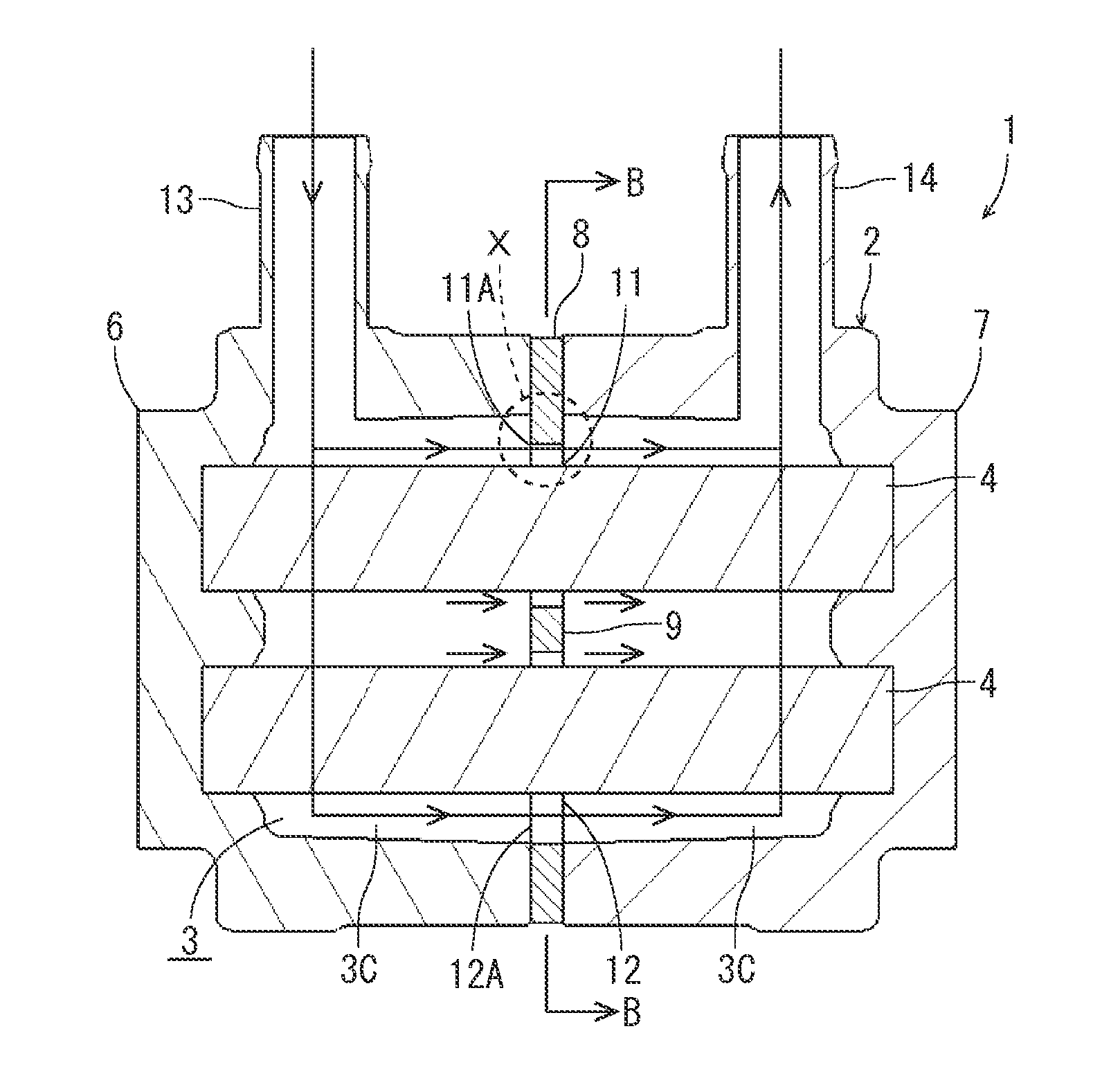
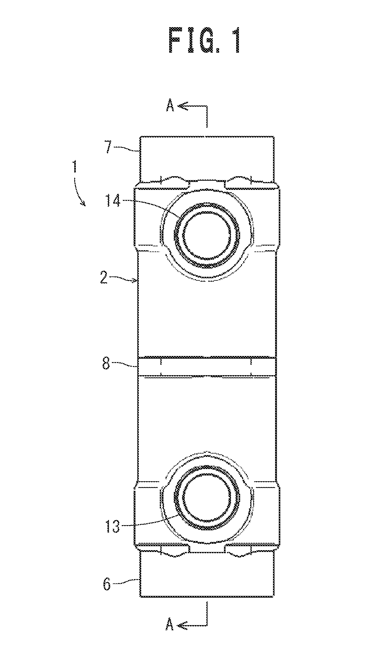
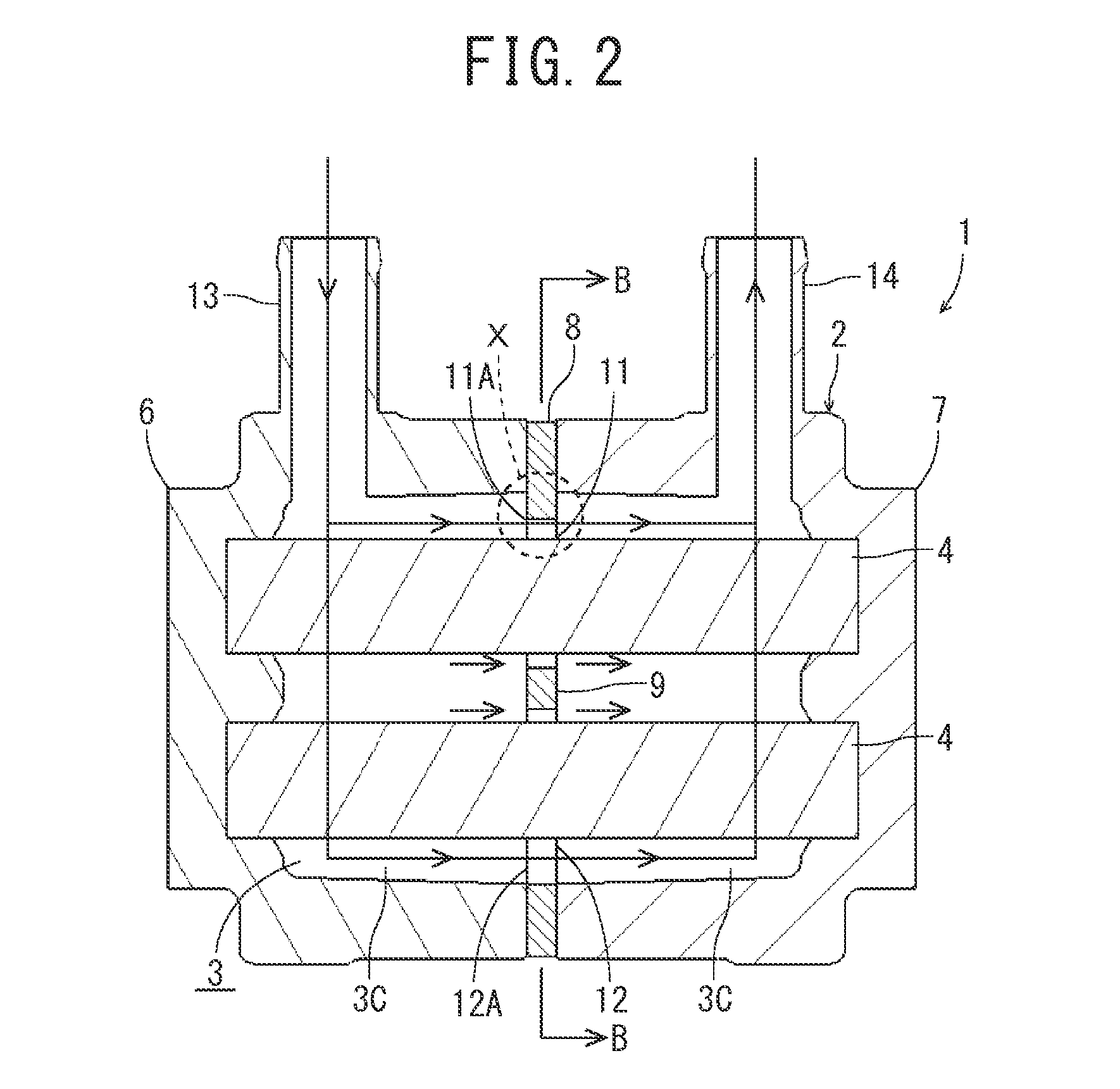
[0045]FIG. 1 to FIG. 6 show a heating device 1 of Embodiment 1 of the present invention. As shown in the respective drawings, the heating device 1 is constituted of a case 2 in which a flow path 3 of a heat medium is constituted, and two electric heating wire heaters 4 as heating elements disposed in the flow path 3 of the case 2.

[0046]The heating device 1 of the embodiment is mounted on a vehicle such as a hybrid car or an electric car, and the heating device is used as a heat source which supplies heat so as to compensate for shortage of waste heat of an engine (the heat source) in the hybrid car, or used as a substitute heat source which supplies the heat in place of the engine which is not present in the electric car, to heat an antifreezing solution (a heat medium) or the like which flows through a water circuit (not shown) of an air conditioning device for the vehicle.

[0047]Specifically, in the hybrid car, an LLC (cooling water or an antifreezing solution) flowing through a co...

embodiment 2

[0063]Next, FIG. 7 to FIG. 9 show another embodiment (Embodiment 2) of the heating device 1 of the present invention. It is to be noted that in the respective drawings, components denoted with the same reference numerals as in FIG. 1 so FIG. 6 produce the same or similar functions. In this case, a shape of a flow path 3 in each of case sections 6 and 7 is a substantially oblong shape as shown in FIG. 7.

[0064]Additionally, in this case, each of passage portions 11 and 12 of a casket 8 possesses a circular shape larger than an outer diameter of each electric heating wire heater 4 so that a predetermined space is present between the passage portion and the electric heating wire heater. Furthermore, as shown in FIG. 8, a plurality of cutout portions 11B projecting to the outside are formed in an upper portion of the upside passage portion 11, and a plurality of cutout portions 12B projecting to the outside are formed also in a lower portion of the downside passage portion 12. The cutout...

embodiment 3

[0068]Next, FIG. 10 and FIG. 11 show still another embodiment (Embodiment 3) of the heating device 1 of the present invention. It is to be noted that in the respective drawings, components denoted with the same reference numerals as in FIG. 1 to FIG. 9 produce the same or similar functions. Also in this case, a shape of a flow path 3 in each of case sections 6 and 7 is a substantially oblong shape as shown in FIG. 7.

[0069]Additionally, in this case, each of passage portions 11 and 12 of a gasket 8 possesses a circular shape larger than an outer diameter of each electric heating wire heater 4 so chat a predetermined space is present between the passage portion and the electric heating wire heater. However, as shown in FIG. 10, a plurality of cutout portions 11C projecting to the outside are formed only in an upper portion of the upside passage portion 11, and the downside passage portion 12 is formed into a circular shape as it is. Furthermore, the cutout portions 11C reach an upside...


PUM


Abstract

Provided is a heating device which makes it possible to effectively perform heat exchange between a heating element and a heat medium without increasing the number of components, and further to eliminate air retention and increase of a pressure loss. A heating device 1 is constituted of a case 2 including therein a flow path 3 through which a heat medium flows, and an electric heating wire heater 4 disposed in the flow path of the case to heat the heat medium. The case comprises a first case section 6 and a second case section 7 each of which has at least one opened surface and which are connected to each other in a state where respective openings are made to abut on each other, and a plate-like gasket 8 which is interposed between abutment portions of the first case section and the second case section, and seals a space between both the case sections, and the gasket controls the flow of the heat medium in the flow path.

Description

TECHNICAL FIELD[0001]The present invention relates to a heating device which heats a heat medium flowing therethrough by use of a heating element.BACKGROUND ART[0002]Due to actualization of environmental problems of recent years, development of hybrid cars and electric cars has been activated and spread thereof has been promoted. In each of such vehicles, waste heat of an engine, which has heretofore been used for air condition in the vehicle cannot sufficiently be utilized. Therefore, a heating device using an electric heating wire heater as a heating element is mounted in the vehicle, and the heating device is used as an auxiliary heat source to compensate for the waste heat of the engine in the hybrid car, or used as a substitute heat source in place of the engine in the electric car, to heat a heat medium such as cooling water which flows through a circuit of an air conditioning device for the vehicle (e.g., see Patent Document 1).[0003]In such a heating device, a flow path thro...

Claims


Application Information

Patent Timeline
IPC IPC(8): F24H1/10
CPCF24H1/103B60H1/2221B60H2001/2271F24H1/009F24H1/102F24H9/0015F24H9/1818F24H2250/02H05B3/04H05B3/24H05B2203/022
Inventor SAKAI, YUSUKEYOKOYAMA, HIROYUKITAGAMI, SHINJI
Owner SANDEN CORP
Features
  • Generate Ideas
  • Intellectual Property
  • Life Sciences
  • Materials
  • Tech Scout
  • Unparalleled Data Quality
  • Higher Quality Content
  • 60% Fewer Hallucinations
Learn More