
System for improving HDMI cec performance, and method for controlling same

a technology of hdmi cec and performance improvement, applied in the field of system for improving hdmi cec performance and controlling same, can solve the problems of inability to describe devices having multiple functions, inability to fit high-speed processing, and inability to clearly define hdmi cec bit timing, etc., to reduce unnecessary use of commands, enhance resource efficiency, and increase the efficiency of bus interface

Inactive Publication Date: 2015-05-14
LG ELECTRONICS INC
View PDF4 Cites 14 Cited by
  • Summary
  • Abstract
  • Description
  • Claims
  • Application Information

AI Technical Summary

Benefits of technology

This patent redefines the operand of HDMI CEC to allow for devices with multiple functions and characteristics to be described and supported by the command set. This reduces the use of commands and increases efficiency. The patent also inserts a sampling period to improve resource utilization and minimize malfunction from incorrect sampling. Additionally, the patent introduces a new mode that enables HDMI CEC to support high-speed transmission and provides a decision protocol for command processing speed. The patent further provides a protocol for allocating various characteristics and a method for expanding logical addresses for management convenience. Furthermore, the patent enables exchange of IP interface information between a bus interface and a PC or mobile device, configuring an integrated topology network for mutual commanding.

Problems solved by technology

However, the present HDMI CES system is inappropriate for description of devices having multiple functions and characteristics.
Further, HDMI CEC bit timing is not clearly defined yet.
Accordingly, it may malfunction due to unnecessary resource waste upon bit sampling and wrong sampling.
Since HDMI CEC using a bus interface supports only insufficient information transmission speed, the HDMI system does not fit high-speed processing and thus fails to back up functions requiring real-time command processing.
The existing bus interface has problems with compatibility or expandability with IP interface that takes up a large part of a home network and is thus limited to performing only independent commands over the home network.

Method used


Image

  • System for improving HDMI cec performance, and method for controlling same
  • System for improving HDMI cec performance, and method for controlling same
  • System for improving HDMI cec performance, and method for controlling same

Examples


Embodiment Construction

[0043]Hereinafter, the configurations and operations of embodiments of the present invention are described with reference to the accompanying drawings. However, such configurations and operations are merely provided as examples, and the technical spirit and core configurations and operations of the present invention are not limited thereto.

[0044]General terms are used in describing the present invention, but in particular cases, some terms are defined by the applicant. Such defined terms are clearly described in a relevant part of the description. Thus, it should be noted that the terms defined herein should be interpreted by referring to the meaning of such terms.

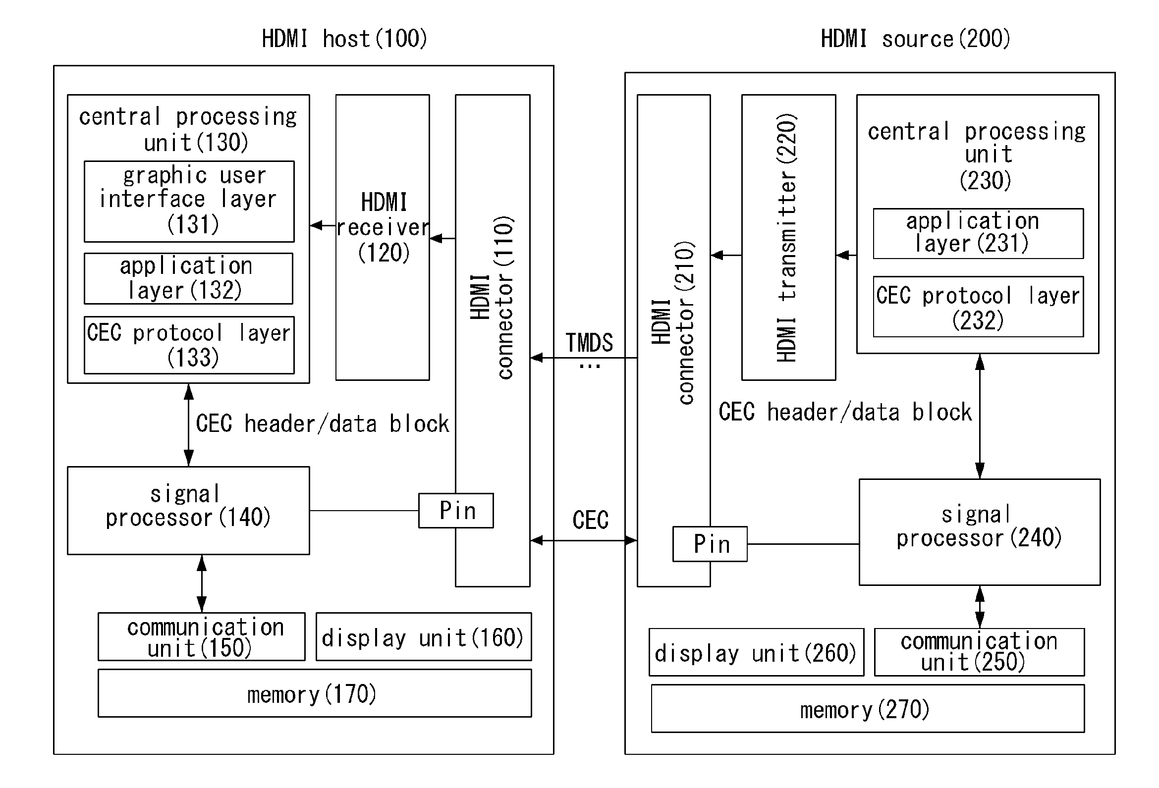
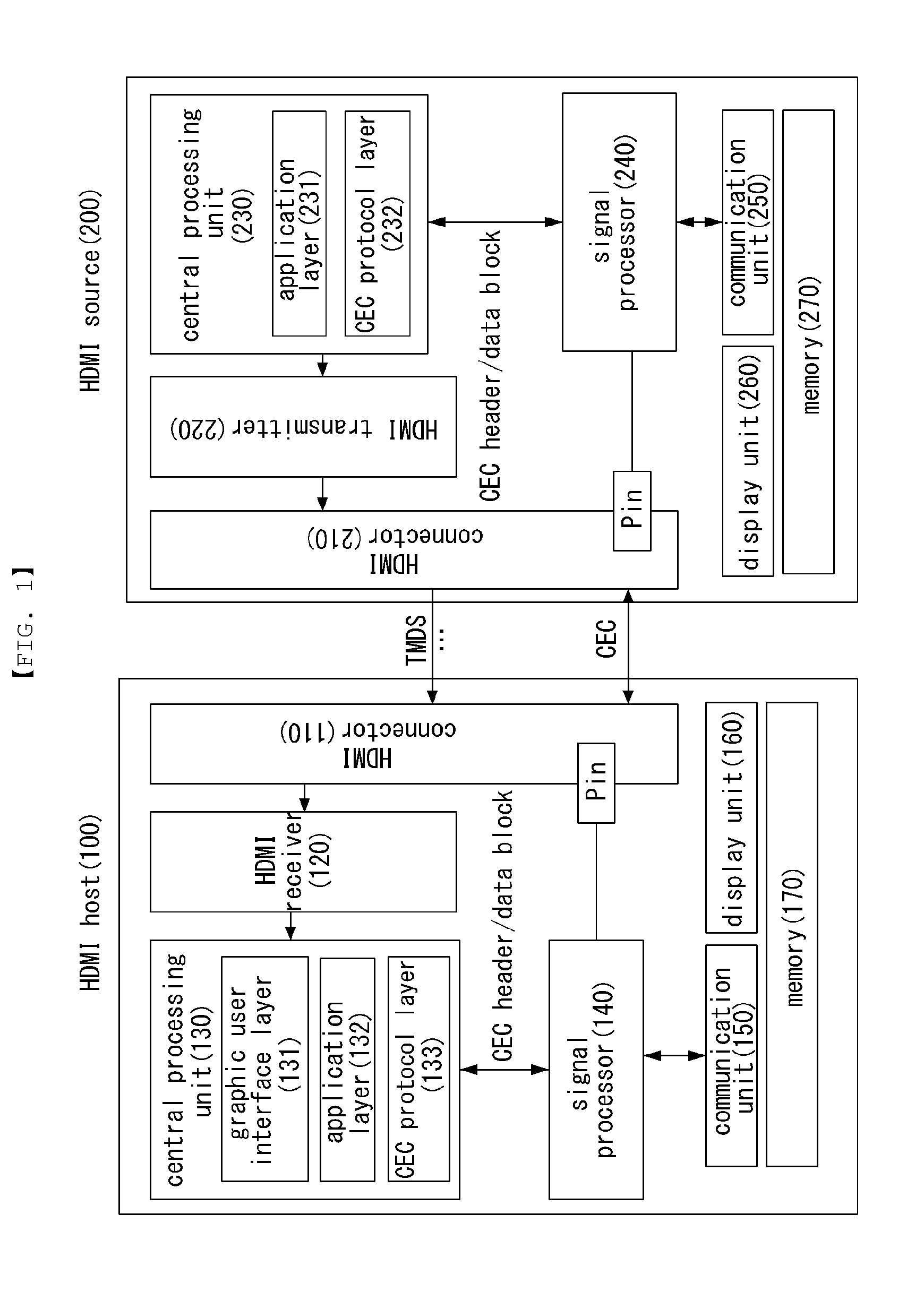
[0045]FIG. 1 is a block diagram schematically illustrating an DL CC system according to an embodiment of the present invention.

[0046]HDMI stands for High-Definition Multimedia Interface and means a multimedia access device that may transmit signals without compression. Hereinafter, such device is denoted as HDMI.

[0047]HDMI...


PUM


Abstract

The present invention provides a method for controlling a HDMI CEC device on HDMI CEC network including a plurality of devices, the method comprising: receiving a message for requesting a physical address allocation of a new device when the new device is connected to the HDMI CEC network; allocating a physical address of the new device based on the received message; and allocating a plural logical addresses of the new device when the physical address of the new device is valid, the plural logical addresses corresponding to the plural device types of the new device, wherein at least one of the plural logical addresses is set by using a flag bit.

Description

TECHNICAL FIELD[0001]The present invention relates to a control method for enhancing the capability of an HDMI CEC system and a device using an HDMI CEC system.BACKGROUND ART[0002]The digital multimedia interface plays a role to transfer video data digitally encoded from a video signal transmitting device, such as an STB, DVR, AVR, or PC, to a TV, monitor, or other video receiving devices. Among digital multimedia interfacing schemes between such AV devices, HDMI (High-Definition Multimedia Interface) is a representative technique that wiredly transmits uncompressed AV data at high speed.[0003]There is recent increasing demand for high-quality videos and 3D videos, such as UHD and 21:9 digital cinema, requiring high-speed data transmission. Further, the requirement for content frame rate is being gradually increased from conventionally 24 / 30 Hz to 60 Hz and 120 Hz to remove video motion blur and after images, and the requirement for color depth that may be represented per pixel is b...

Claims


Application Information

Patent Timeline
Patent Type & Authority Applications(United States)
IPC IPC(8): G06F13/10G06F13/42
CPCG06F13/4221G06F13/102H04N21/436H04N21/43635H04N21/6402G06F3/14G09G5/006G09G2370/025G09G2370/06G09G2370/12
Inventor LEE, JAEKOOLEE, HYEONJAEYANG, SEUNGRYUL
Owner LG ELECTRONICS INC
Learn More