
Resonator element, resonator, oscillator, electronic apparatus, and mobile object

a resonator element and oscillator technology, applied in the direction of oscillator, force measurement, instruments, etc., can solve the problems of inability to obtain a resonator element with a favorable vibration characteristic, leakage cannot be sufficiently minimized, etc., and achieve the effect of high reliability

Active Publication Date: 2015-05-21
SEIKO EPSON CORP
View PDF35 Cites 5 Cited by
  • Summary
  • Abstract
  • Description
  • Claims
  • Application Information

AI Technical Summary

Benefits of technology

The patent describes a resonator element that can minimize vibration leakage and provide high reliability. It has excellent impact resistance and can reduce vibration leakage by using a fixed portion and a support arm to lengthen the separation distance between the fixed portion and the vaging arm. This design also improves the quality of the resonator by reducing deterioration in the Q value due to air resistance. Additionally, this resonator element can be used in a mobile object with high reliability.

Problems solved by technology

However, even if the ratio e / r is satisfied, there is a case where the vibration leakage cannot be sufficiently minimized and a resonator element with a favorable vibration characteristic cannot be obtained, depending on design conditions (for example, a thickness of the resonator blank).

Method used


Image

  • Resonator element, resonator, oscillator, electronic apparatus, and mobile object
  • Resonator element, resonator, oscillator, electronic apparatus, and mobile object
  • Resonator element, resonator, oscillator, electronic apparatus, and mobile object

Examples


first embodiment

[0108]First, a resonator according to a first embodiment of the invention will be described.

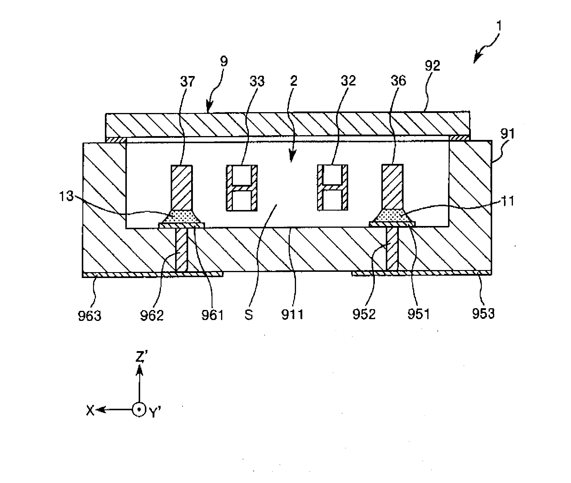
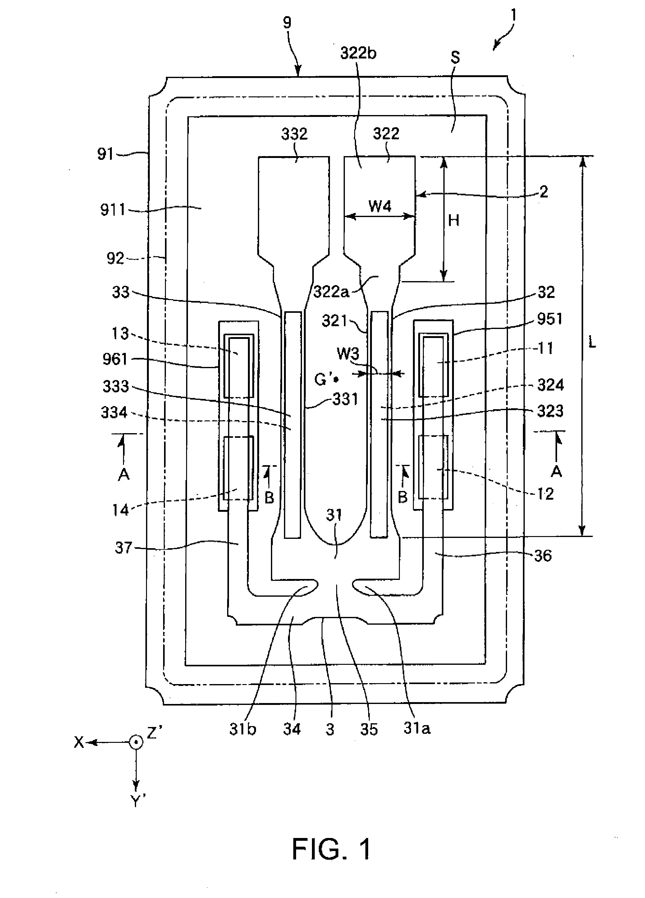
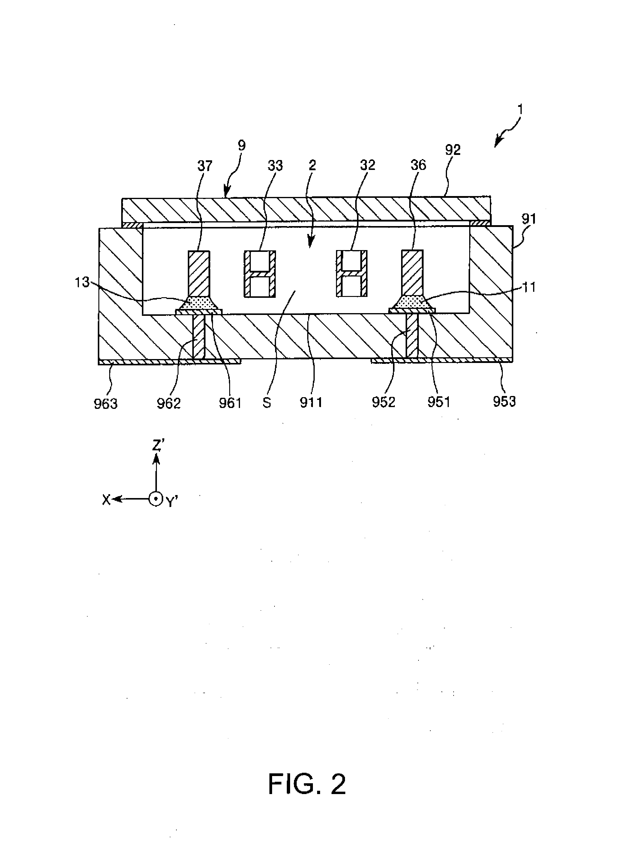
[0109]FIG. 1 is a plan view illustrating the resonator according to the first embodiment of the invention. FIG. 2 is a cross-sectional view taken along the line A-A of FIG. 1. FIG. 3 is a cross-sectional view taken along the line B-B of FIG. 1. FIG. 4 is a cross-sectional view illustrating a vibrating arm which is formed through wet etching. FIG. 5 is a cross-sectional view of the vibrating arm for explaining thermal conduction during flexural vibration. FIG. 6 is a graph illustrating a Q value and f / fm. FIG. 7 is a perspective view illustrating a thickness T, and widths W1 and W2. FIG. 8 is a plan view illustrating dimensions of a quartz crystal resonator blank used in a simulation. FIG. 9 is a perspective view for explaining a simulation method. FIGS. 10 to 13 are tables illustrating simulation results. FIG. 14 is a graph illustrating a relationship between W2 / W1 and QLeak. FIG. 15 is a gra...

second embodiment

[0171]FIG. 35 is a plan view of a resonator according to a second embodiment of the invention. FIG. 36 is a cross-sectional view taken along the line C-C of FIG. 35. FIG. 37 is a plan view of a resonator element included in the resonator illustrated in FIG. 35. FIG. 38A is a cross-sectional view taken along the line D-D of FIG. 37. FIG. 38B is a cross-sectional view taken along the line E-E of FIG. 37. FIG. 39 is a partially enlarged plan view illustrating a base portion of the resonator element illustrated in FIG. 37.

[0172]Hereinafter, the second embodiment will be described focusing on a difference from the above-described embodiment, and description of the same content will be omitted.

[0173]The second embodiment is the same as the first embodiment except for a difference in a configuration of a resonator element.

[0174]As illustrated in FIGS. 35 and 36, a resonator 1 includes a resonator element 4 and a package 9 which stores the resonator element 4 therein. Hereinafter, the reson...


PUM


Abstract

A resonator element includes a resonator blank having a base portion, a vibrating arm, a linking portion, and a connecting portion connects the base portion and the linking portion to each other, in which, when a thickness of the resonator blank is set to T, a width of the base portion is set to W1, and a width of the connecting portion is set to W2, a relationship of 50 μm≦T≦210 μm is satisfied, and a relationship of 0.067≦W2 / W1≦0.335 is satisfied, and in which, when a width of the arm section of the vibrating arm is set to W3, and a width of the hammer head is set to W4, a relationship of W4≧2.8×W3 is satisfied.

Description

CROSS REFERENCE[0001]The entire disclosures of Japanese Patent Application No. 2013-237480, filed Nov. 16, 2013, Japanese Patent Application No. 2013-237476, filed Nov. 16, 2013, and Japanese Patent Application No. 2013-237477, filed Nov. 16, 2013, are expressly incorporated by reference herein.BACKGROUND[0002]1. Technical Field[0003]The present invention relates to a resonator element, a resonator, an oscillator, an electronic apparatus, and a mobile object.[0004]2. Related Art[0005]In the related art, a resonator element using a quartz crystal is known. Such a resonator element has excellent frequency-temperature characteristics and is thus widely used as a reference frequency source or a transmission source of various electronic apparatuses.[0006]A resonator element disclosed in JP-A-2008-72705 is a tuning fork type and has a resonator element (also referred to as a resonator blank) which includes a base portion, a pair of vibrating arms which extend from one end side of the base...

Claims


Application Information

Patent Timeline
Patent Type & Authority Applications(United States)
IPC IPC(8): H03H9/15
CPCH03H9/15H03H9/02157G01L1/106H03B5/32H03H3/04H03H9/0509H03H9/0547H03H9/21H03H9/215
Inventor YAMADA, AKINORIYAMAZAKI, TAKASHI
Owner SEIKO EPSON CORP
Learn More