Magnetic circuit and coaxial speaker using the same

a coaxial speaker and magnetic flux technology, applied in the direction of transducer details, electrical transducers, electrical apparatus, etc., can solve the problems of severe magnetic flux leakage at the opposite lateral side, and the design of coaxial speakers does not meet the requirements of the electronic market, so as to reduce the overall size of the speaker and reduce the leakage of magnetic flux

Active Publication Date: 2015-05-21
MERRY ELECTRONICS SUZHOU
View PDF2 Cites 18 Cited by
  • Summary
  • Abstract
  • Description
  • Claims
  • Application Information

AI Technical Summary

Benefits of technology

[0006]The present invention has been accomplished under the circumstances in view. It is the main object of the present invention to provide a magnetic circuit and a coaxial speaker using the magnetic circuit, which enables the magnetic units of multiple drivers to shape a common magnetic loop, reducing magnetic flux leakage and the overall size of the speaker.
[0008]Thus, the at least one second magnetic unit can be shared by the first magnetic loop and the second magnetic loop, achieving effective use of the magnetic fields at the two sides of the at least one second magnetic unit to reduce magnetic flux leakage and providing a uniform magnetic field distribution.
[0010]Thus, the diaphragms and voice coils of the inner and outer drivers are respectively drivable by the first magnetic loop and the second magnetic loop to output sounds in different audio frequency ranges. Further, the inner and outer drivers share the common second magnetic unit, facilitating the overall size of the coaxial speaker.

Problems solved by technology

Obviously, this design of coaxial speaker does not meet the requirements of the electronic market.
However, a regular magnetic circuit simply uses the magnetic field at one lateral side of the magnet, as shown in FIG. 2, and a severe magnetic flux leakage can occur at the opposite lateral side.

Method used


Image

  • Magnetic circuit and coaxial speaker using the same
  • Magnetic circuit and coaxial speaker using the same
  • Magnetic circuit and coaxial speaker using the same

Examples


Embodiment Construction

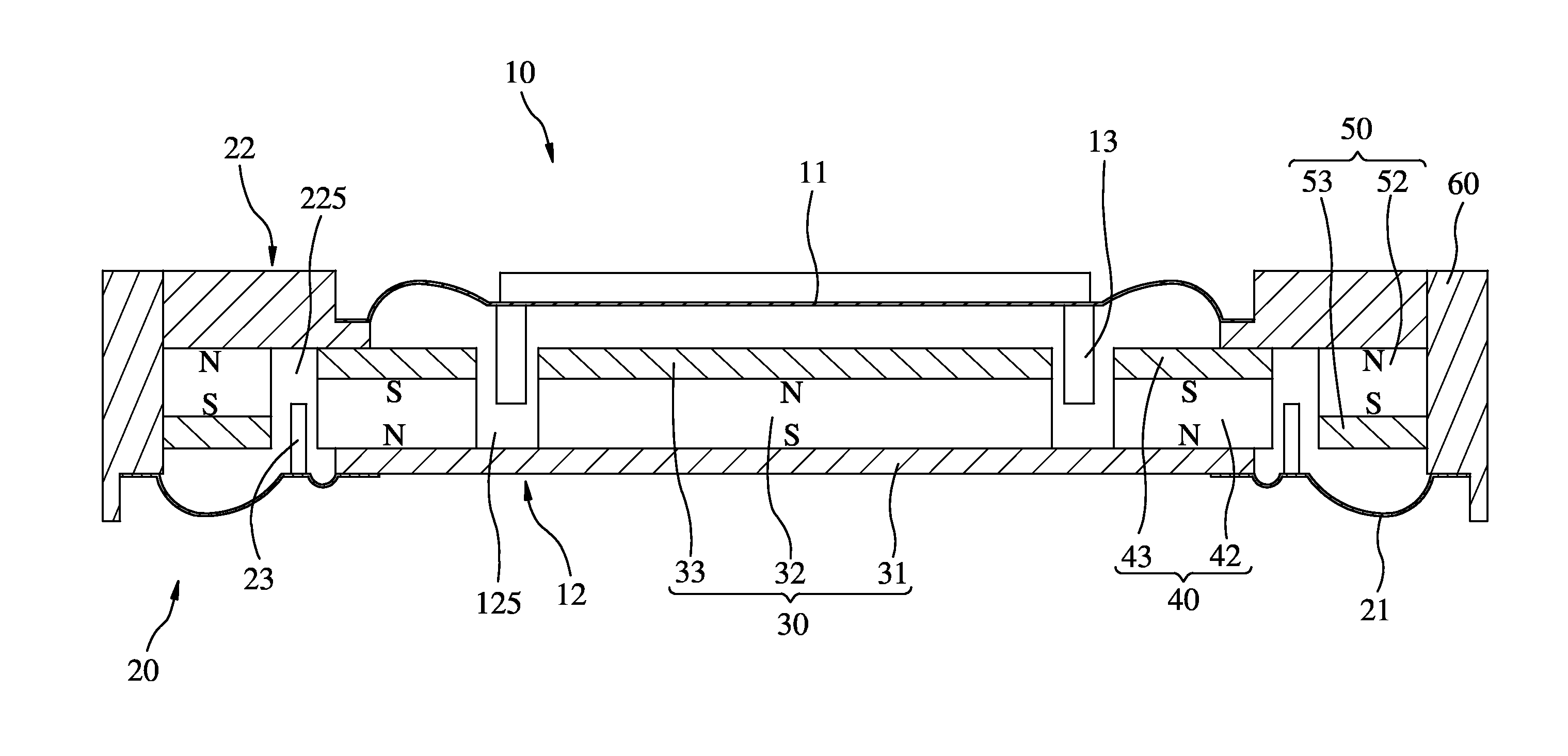
[0019]For easily understanding the structural details and features of the present invention, a first embodiment is provided in the form of a coaxial speaker. As illustrated in FIGS. 3 and 4, the coaxial speaker comprises a cabinet 60, an inner driver 10 and an outer driver 20 coaxially accommodated in the cabinet 60. The inner driver 10 is adapted for the output of a low frequency range. The outer driver 20 is adapted for the output of a high frequency range.

[0020]Referring to FIG. 3, the inner driver 10 comprises an inner diaphragm 11, a first magnetic loop 12, and an annular outer voice coil 13. The annular outer voice coil 13 is mounted at one side of the inner diaphragm 11 and partially received within the first magnetic loop 12, enabling the first magnetic loop 12 to produce a magnetic field induction with the electric current passing through the inner voice coil 13 and to further drive the inner diaphragm 11 to vibrate. The first magnetic loop 12 is formed of a first magnetic ...


PUM


Abstract

A magnetic circuit for coaxial speaker includes a first magnetic unit, at least one second magnetic unit arranged around the first magnetic unit and at least one third magnetic unit arranged around the at least one second magnetic unit. The magnetic pole arrangement of the second magnetic unit is reversed to the magnetic pole arrangement of the first magnetic unit and the second magnetic unit, enabling a first magnetic loop to be established between the first magnetic unit and the at least one second magnetic unit and a second magnetic loop to be established between the at least one second magnetic unit and the at least one third magnetic unit. The magnetic circuit is practical for use in the inner and outer drivers of a coaxial speaker, providing uniform magnetic field distribution, and facilitating speaker miniaturization.

Description

BACKGROUND OF THE INVENTION[0001]1. Field of the Invention[0002]The present invention relates to a magnetic circuit for use in a coaxial speaker, and more particularly, to a magnetic circuit that shares a common magnetic loop and is capable of providing a uniform magnetic field distribution, improving the voice coil driving efficiency and effectively reducing the overall size of the speaker.[0003]2. Description of the Related Art[0004]With increasing competitiveness in today's electronic product market, is becoming more competitive, every manufacturer requirements on the specifications of speaker for electronic products have become more critical than ever. Not only hope the speaker size to be more compact size to fit thin electronic product design, but also want the speaker to provide a wide range of audio output. It is therefore often necessary to install a second driver, promoting the creation of coaxial speaker.[0005]Various coaxial speakers are known. For example, a conventional...

Claims


Application Information

Patent Timeline
Patent Type & Authority Applications(United States)
IPC IPC(8): H04R9/02H04R7/16H04R9/04
CPCH04R9/025H04R7/16H04R9/04H04R1/24
Inventor LAI, TSAI-TICHEN, CHUN-PINWANG, WEN-HONG
Owner MERRY ELECTRONICS SUZHOU
Why Eureka
Try Eureka