Coded image system and method thereof

Active Publication Date: 2015-05-21
BAE SYST INFORMATION & ELECTRONICS SYST INTERGRATION INC
View PDF12 Cites 38 Cited by
  • Summary
  • Abstract
  • Description
  • Claims
  • Application Information

AI Technical Summary

Benefits of technology

The present invention provides a method for improving the quality of images captured using a separable optics system. The method involves using a doubly-Toeplitz mask to create an encoded image, which is then decoded to recover a larger visual representation of the object scene. The recovered object scene is displayed in a monitor. The decoding process includes filtering the encoded image to remove image variations, regularizing the decoding, and iterating the encoded image to reduce numerical round-off errors. The invention also provides a method for improving the quality of images captured using any system with separable optics by applying the mathematical methods outlined herein.

Problems solved by technology

The effect often cited (by other researchers) as an impediment—diffraction—proved to be a minor problem when doubly-Toeplitz masks are used for the coded apertures.
The major effects turned out to be due to device characteristics: defects and non-uniformity of the image plane array, and light leakage through the “off” elements of the SLM, and the consequent reflections of that light inside the camera, especially from the micro-lenses covering each image-array pixel.
For example, the Tikhonov regularization constant α helps reduce noise in the reconstruction, but setting this value too high causes undue blurring of the reconstructed scene.

Method used


Image

  • Coded image system and method thereof
  • Coded image system and method thereof
  • Coded image system and method thereof

Examples


Embodiment Construction

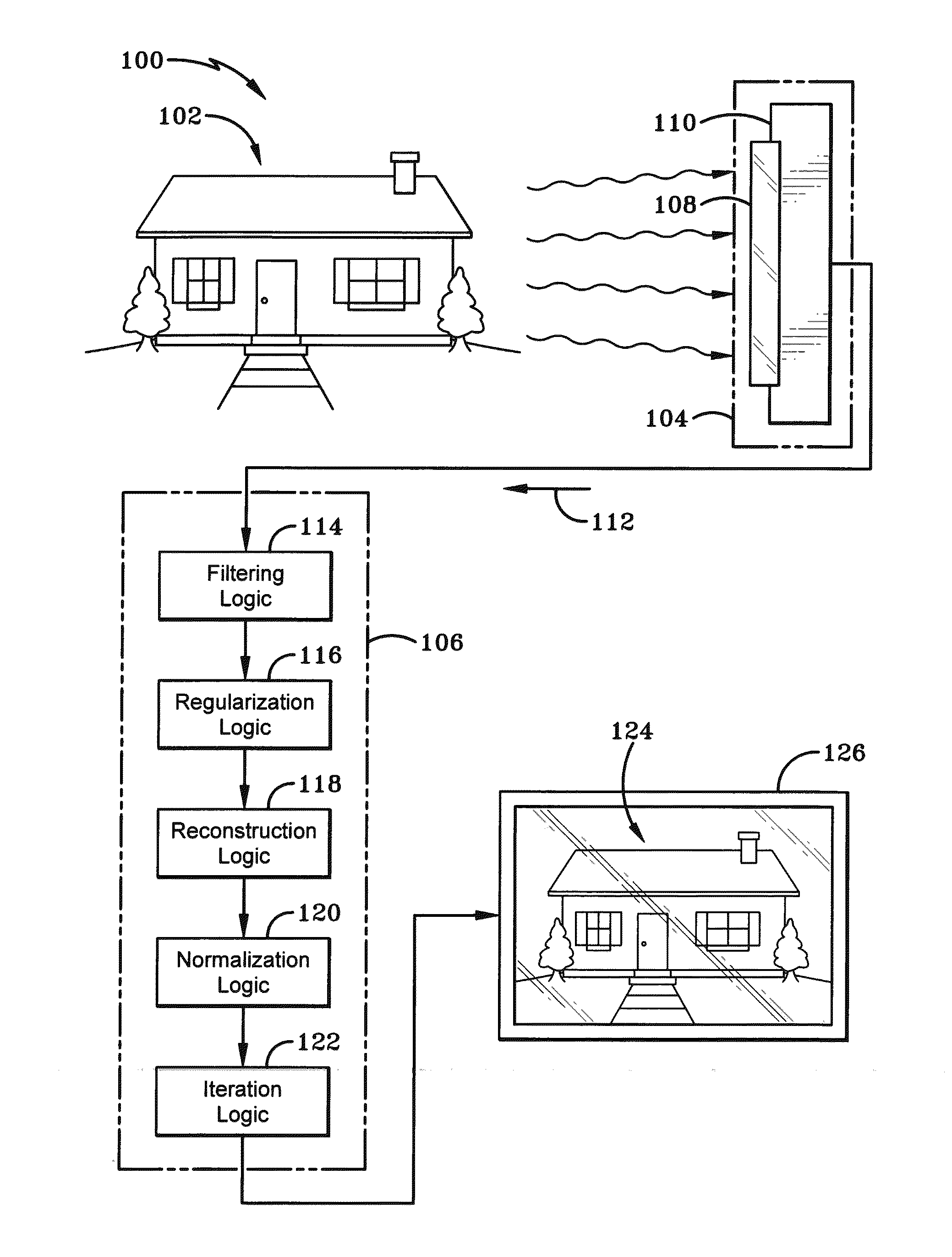
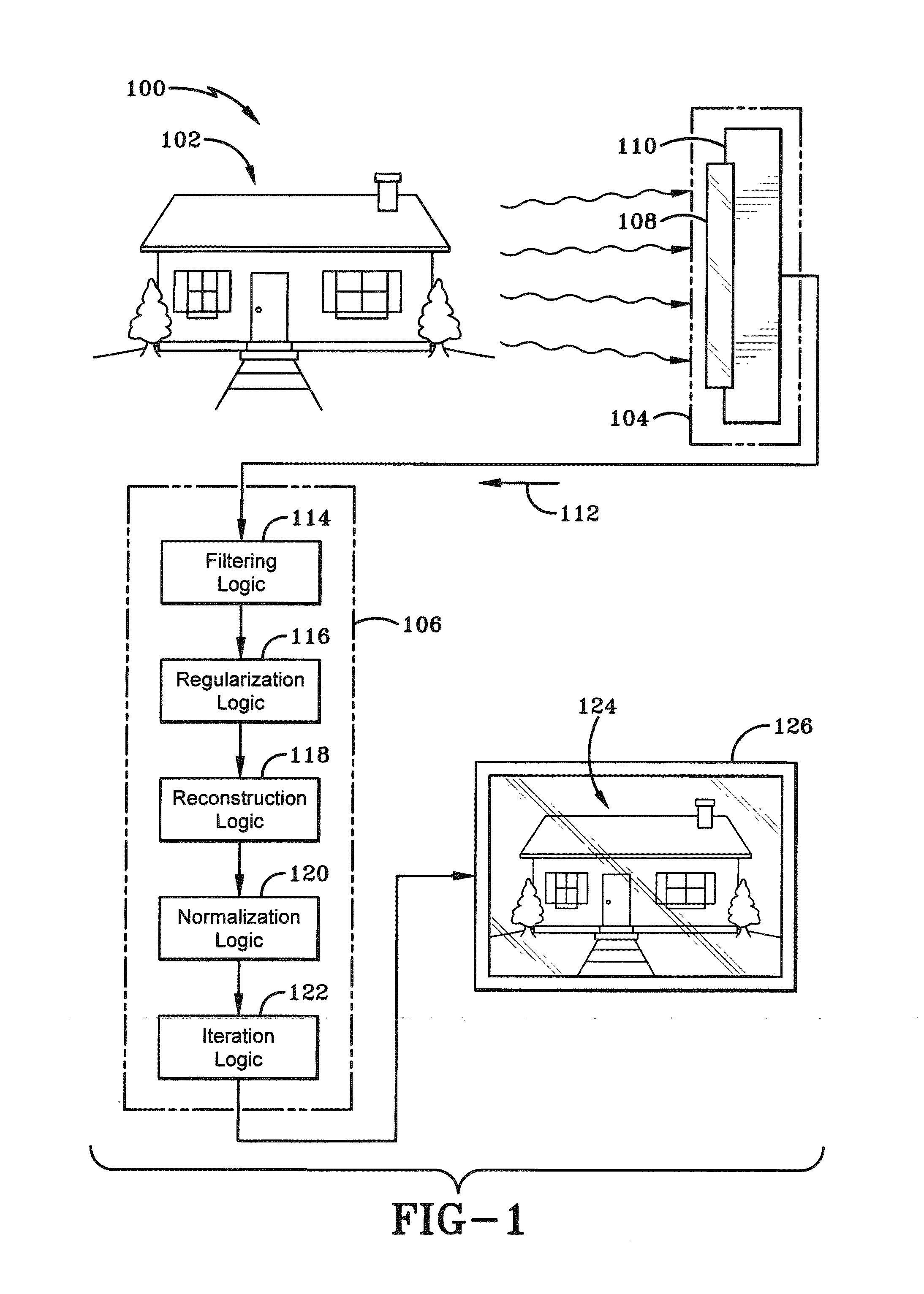
[0037]As depicted in FIG. 1, a coded image system of the present invention is depicted generally at 100. The image system 100 comprises a physical object scene 102, an encoding logic 104, and a decoding logic 106. The encoding logic 104 includes a programmable aperture mask 108 electronically coupled with a camera or imager 110 spaced a distance away from the physical object scene 102. Mask 108 receives light waves partially therethrough, as will be discussed in greater detail below. The encoding logic 104 creates an encoded image 112 via a doubly-Toeplitz matrix programmed on mask 108, the doubly-Toeplitz matrix produced by two one-dimensional vectors as will be described further below. The decoding logic 106 is configured to decode the encoded image recovering a visual representation 124 of the object scene from the encoded image. The decoding logic includes a filtering logic 114, a regularization logic 116, a reconstruction logic 118, a normalization logic 120, and a iteration lo...


PUM


Abstract

A coded image system enables a user to recover an object scene from an encoded image. The coded the image system comprises: a physical object scene; an encoding logic creating an encoded image, the encoding logic including a programmable aperture mask spaced a distance away from the physical object scene to encode the encoded image via a doubly-Toeplitz matrix, the doubly-Toeplitz matrix including two one-dimensional vectors; and a decoding logic operatively coupled to the programmable aperture mask to decode the encoded image recovering a visual representation of the object scene from the encoded image.

Description

CROSS-REFERENCE TO RELATED APPLICATION[0001]This application claims priority from U.S. Provisional Application Ser. No. 61 / 906,958, filed Nov. 21, 2013, the disclosure of which is incorporated herein by reference.STATEMENT OF GOVERNMENT INTEREST[0002]This invention was made with US Government assistance under Contract No. N00014-10-C-0193 awarded by the Office of Naval Research (ONR). The US Government has certain rights in this invention.BACKGROUND OF THE INVENTION[0003]1. Field of the Invention[0004]The present invention relates generally to devices, methods, and systems of coded images. More particularly, an aspect of the present invention relates to lensless imaging and to spatially coded imaging.[0005]2. Brief Description of Prior Developments[0006]Fixed (non-programmable) coded-aperture technology and programmable masks realized with Spatial Light Modulators were heretofore known in the art. The SLM elements are controlled so that the modulated transmission forms an aperture m...

Claims


Application Information

Patent Timeline
IPC IPC(8): H04N19/44
CPCH04N19/44H04N19/42
Inventor DEWEERT, MICHAEL J.FARM, BRIAN P.TOPPING, MILES
Owner BAE SYST INFORMATION & ELECTRONICS SYST INTERGRATION INC
Why Eureka
Try Eureka