Hydrocarbon Well Performance Monitoring System

a technology of hydraulic wells and monitoring systems, which is applied in the direction of survey, instruments, borehole/well accessories, etc., can solve the problems of ineffective direct monitoring, high force and pressure involved in pumping operation, and high cost of drilling, assembling and servicing such wells

Active Publication Date: 2015-05-21
MCCOY JAMES N
View PDF8 Cites 44 Cited by
  • Summary
  • Abstract
  • Description
  • Claims
  • Application Information

AI Technical Summary

Benefits of technology

[0016]The need in the art is addressed by the methods of the present invention. The present invention teaches a method for real-time data acquisition and generation of a position and force surface card for a subterranean well pumping system. This method provides for real-time acquisition and presentation by a processor of performance data, which is associated with a pump lifting well fluids from a subterranean well to a surface level, the is pump reciprocated by a rod extending upward to a cyclical drive unit at the surface level, and where the rod includes a polished rod fixed the

Problems solved by technology

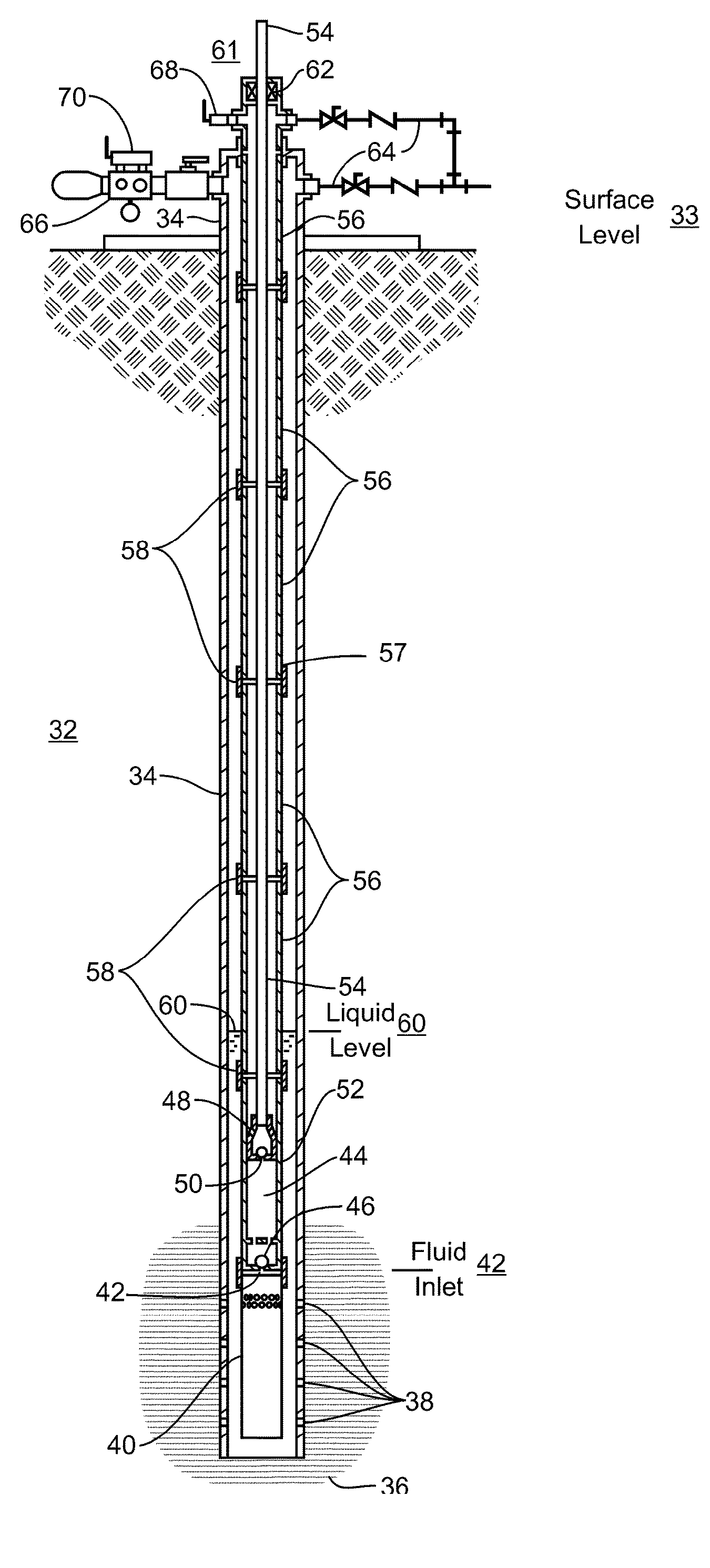
Since wells range in depths to many thousand feet, the forces and pressures involved in the pumping operation are substantial.
The costs of drilling, assembling, and servicing such wells are also substantial.
However, many of the critical pumping components are installed deep into the well's borehole, referred to as “down-hole”, where direct monitoring is not economically practical.
Since failure of a system component down-hole can have catastrophic implications both in terms of repair costs and lost production, well operators have long sought equipment and techniques for assessing down-hole operation and performance.
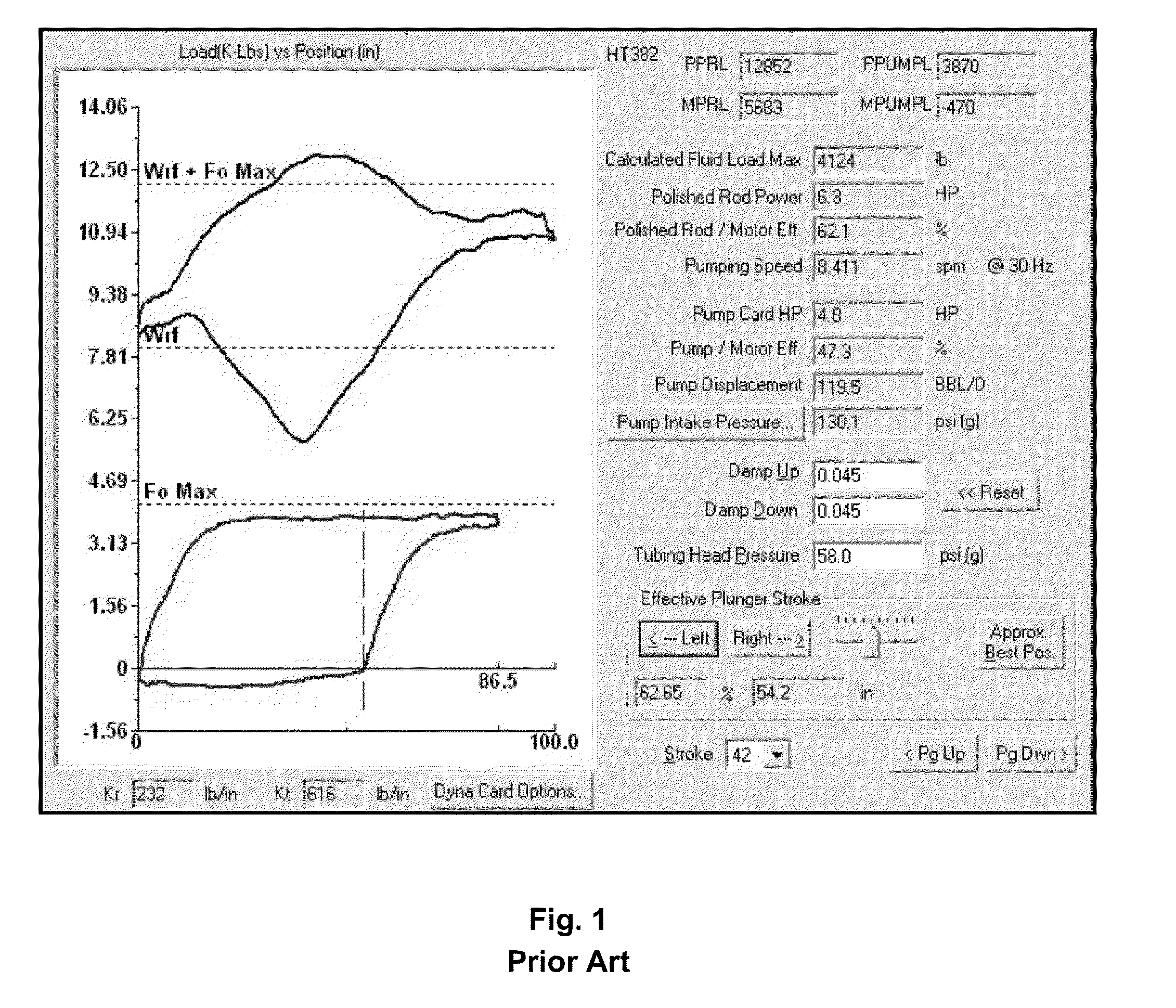
Experienced operators can, to a limited degree, extrapolate from trends in surface card plots over time to infer potential problems occurring down-hole, although this approach remains substantially subjective.
The petroleum formation reservoir may be providing insufficient liquid to fill the pump.
Or, there may be a mechanical failure of the rod string, tubing string, a valve leakage, plunger slippage, inadequate de

Method used


Image

  • Hydrocarbon Well Performance Monitoring System
  • Hydrocarbon Well Performance Monitoring System
  • Hydrocarbon Well Performance Monitoring System

Examples


Embodiment Construction

[0069]Illustrative embodiments and exemplary applications will now be described with reference to the accompanying drawings to disclose the advantageous teachings of the present invention.

[0070]While the present invention is described herein with reference to illustrative embodiments for particular applications, it should be understood that the invention is not limited thereto. Those having ordinary skill in the art and access to the teachings provided herein will recognize additional modifications, applications, and embodiments within the scope hereof and additional fields in which the present invention would be of significant utility.

[0071]In considering the detailed embodiments of the present invention, it will be observed that the present invention resides primarily in combinations of steps to accomplish various methods or components to form various apparatus and systems. Accordingly, the apparatus and system components and method steps have been represented where appropriate by...


PUM


Abstract

A system and method for real-time data acquisition and presentation of force, position, load, pressures, and movement within a subterranean well pumping system, such as an oil well. Data is gathered using sensors attached to a surface level pump drive and wellhead system. Well structural data and well production data are combined therewith to generate a real-time display of down-hole well operation, including animated graphics of the pump operation, including pump movement, rod and tubing stretch, fluid movement, gas compression, system forces, and fluid pressures. Liquid levels are tested using an acoustic liquid level instrument, and incorporated to improve well performance analysis.

Description

RELATED APPLICATION[0001]This is a Divisional application from U.S. application Ser. No. 13 / 334,385 filed on Dec. 22, 2011.BACKGROUND OF THE INVENTION[0002]1. Field of the Invention[0003]The present invention relates to monitoring the operation and performance of sucker rod pumped wells. More particularly, the present invention relates to systems that employ dynamometers, acoustic level measuring devices, and pressure sensors in conjunction with a computer to monitor in real-time, record, and display a wide range of information about various operational parameters in oil and gas wells that employ a sucker rod pump.[0004]2. Description of the Related Art[0005]Most wells utilize a pumping system to extract oil, gas, and water from subterranean well boreholes. The pumping system typically comprises a surface mounted reciprocating drive unit coupled to a submerged pump by a long steel rod, referred to as a sucker-rod. The submerged pump consists of a chamber, plunger, and a pair of chec...

Claims


Application Information

Patent Timeline
IPC IPC(8): E21B49/00E21B47/04E21B47/06E21B47/00
CPCE21B49/003E21B47/06E21B47/042E21B47/0007E21B47/009E21B47/13E21B47/008E21B47/047E21B43/127E21B41/00E21B49/08G01L5/0061G01P7/00E21B49/00G01P15/00
Inventor MCCOY, JAMES N.
Owner MCCOY JAMES N
Why Eureka
Try Eureka