Computer implemented system and method for generating a layout of a cell defining a circuit component

a technology of circuit components and computer implementation, which is applied in the direction of specific program execution arrangements, instruments, program control, etc., can solve the problems of complex design rules, significant complexity of the techniques used to develop each of the process layers, and the inability to meet the requirements of the design of the standard cell for emerging process technologies

Active Publication Date: 2015-05-21
ARM LTD
View PDF15 Cites 82 Cited by
  • Summary
  • Abstract
  • Description
  • Claims
  • Application Information

AI Technical Summary

Benefits of technology

[0017]In a further example, there is provided a non-transitory storage medium storing a cell library containing one or more cell layouts generated in accordance with the above-described cell layout generation method.

Problems solved by technology

However, as the process technologies reduce below the 20 nm technology, for example in to the 14 nm domain, then the techniques used to develop each of the process layers become significantly more complex.
This results in the design rules becoming far more complicated than has traditionally been the case, setting out not only the three basic rules discussed earlier, but also requiring the specification of many different examples and exceptions.
This has the result that the design of standard cells for emerging process technologies is becoming very complex.
Further, at such process technologies it is no longer the case that a new variant of a particular component can readily be produced merely by a relatively simple modification to an existing standard cell.
The above described problems associated with the generation of standard cells apply also to the generation of other types of cells.

Method used


Image

  • Computer implemented system and method for generating a layout of a cell defining a circuit component
  • Computer implemented system and method for generating a layout of a cell defining a circuit component
  • Computer implemented system and method for generating a layout of a cell defining a circuit component

Examples


Embodiment Construction

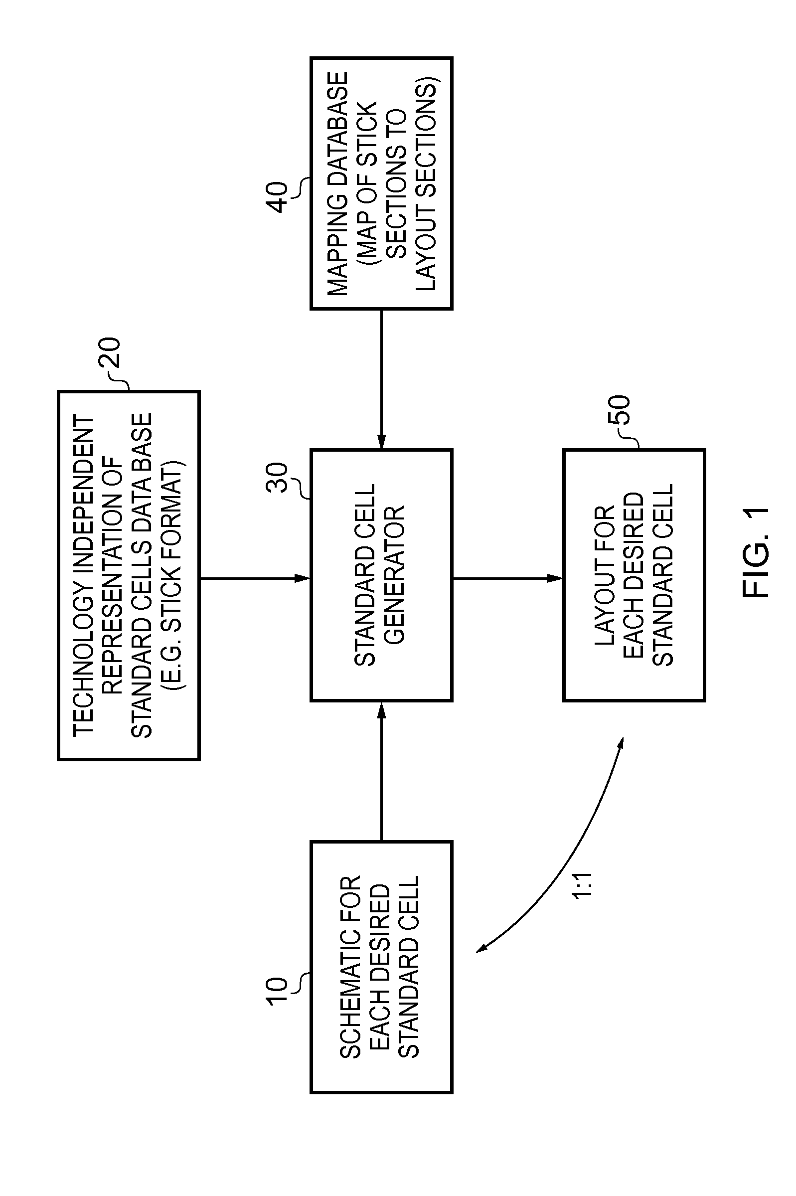
[0061]Before discussing the embodiments with reference to the accompanying figures, the following description of embodiments is provided. In one example, there is provided a computer implemented method of generating a layout of a cell defining a circuit component, the layout providing a layout pattern for a target process technology, the method comprising: obtaining an archetype layout providing a valid layout pattern for the cell having regard to design rules of the target process technology; receiving an input data file providing a process technology independent schematic of the circuit component for which the cell is to be generated; performing a schematic sizing operation on the input data file, having regard to schematic constraints applicable to the target process technology and layout constraints derived from the archetype layout, in order to generate an output data file providing a process technology dependent schematic of the circuit component; performing a cell generation ...


PUM


Abstract

A computer implemented system and method is provided for generating a layout of the cell defining a circuit component, the layout providing a layout pattern for a target process technology. The method comprises obtaining an archetype layout providing a valid layout pattern for the cell having regard to design rules of the target process technology, and receiving an input data file providing a process technology independent schematic of the circuit component for which the cell is to be generated. A schematic sizing operation is then performed on the input data file, having regard to both schematic constraints applicable to the target process technology and layout constraints derived from the archetype layout, in order to generate an output data file providing a process technology dependent schematic of the circuit component. A cell generation operation is then performed using the output data file and layout data determined from the archetype layout in order to generate the layout of the cell. Such an approach enables both the schematic and layout to be co-optimised during generation of the layout of the cell.

Description

RELATED CASES[0001]This application claims priority to U.S. provisional patent Application No. 61 / 906,237 filed on 19 Nov. 2013, and U.S. application Ser. No. 14 / 165,623 filed on 28 Jan. 2014, the entire contents of each of which are incorporated herein by reference.BACKGROUND[0002]1. Field[0003]The present technique relates to a computer implemented system and method for generating a layout of a cell defining a circuit component.[0004]2. Description of the Prior Art[0005]When producing integrated circuits, a number of process layers are formed on a substrate, each process layer incorporating a layout pattern. The layout patterns within the various layers establish component features and interconnections such that once the final process layer has been formed, an integrated circuit has been produced containing all of the required circuit components interconnected in the manner required to perform the functions of the integrated circuit.[0006]For a new integrated circuit, a layout of ...

Claims


Application Information

Patent Timeline
Patent Type & Authority Applications(United States)
IPC IPC(8): G06F17/50
CPCG06F17/5081G06F17/5045G06F30/39G06F30/30G06F30/398G06F30/392G06F30/394
Inventor DE DOOD, PAULFREDERICK, MARLIN WAYNEWANG, JERRY CHAOYUANLEE, BRIAN DOUGLAS NGAI
Owner ARM LTD
Why Eureka
Try Eureka