Turbo rotational frequency detection device

a technology of rotation sensor and turbocharger, which is applied in the direction of machines/engines, electric control, instruments, etc., can solve the problems of increasing the number of cases, no spatial room left, and the difficulty of arranging the rotation sensor at the bearing portion between the turbine and the turbocharger as ever, so as to achieve excellent effects and reduce costs

Inactive Publication Date: 2015-05-28
HINO MOTORS LTD
View PDF2 Cites 9 Cited by
  • Summary
  • Abstract
  • Description
  • Claims
  • Application Information

AI Technical Summary

Benefits of technology

[0020]Excellent effects can be obtained according to the above-mentioned turbo rotational frequency detection device of the invention. Without a rotation sensor at a bearing portion between a turbine and a compressor of a turbocharger, a rotational frequency of the turbocharger can be determined by physical calculations on the basis of entry and exit pressures of the compressor and mass flow rate and

Problems solved by technology

In association with such downsizing concept being becoming main stream, further compactification in size of turbochargers has been demanded, which makes it difficult to arrange a rotation sensor at a bearing portion between a turbine and a compressor of a

Method used


Image

  • Turbo rotational frequency detection device
  • Turbo rotational frequency detection device
  • Turbo rotational frequency detection device

Examples


Embodiment Construction

[0024]An embodiment of the invention will be described in conjunction with the drawings.

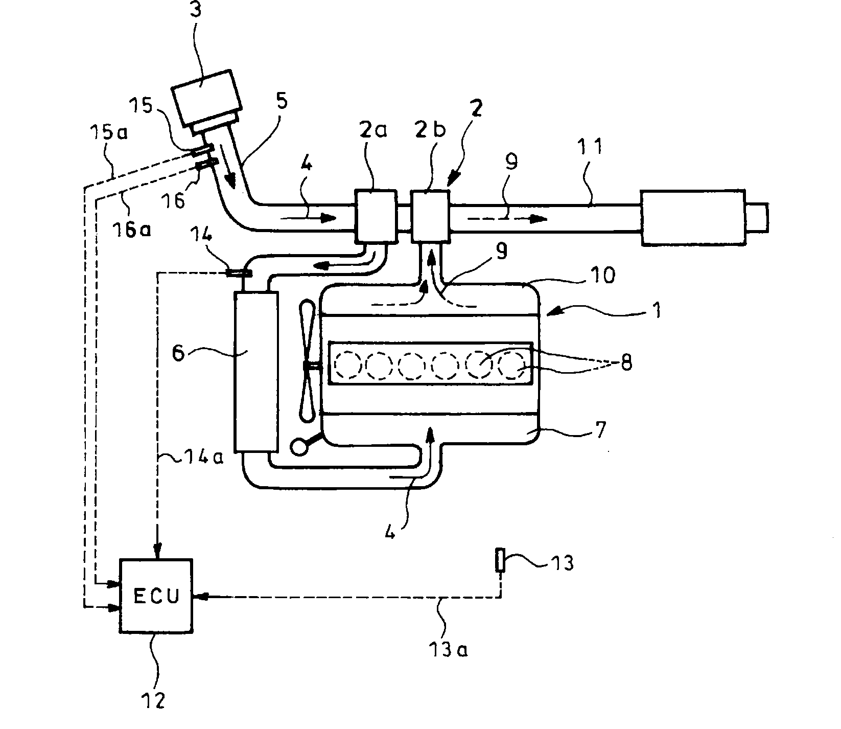
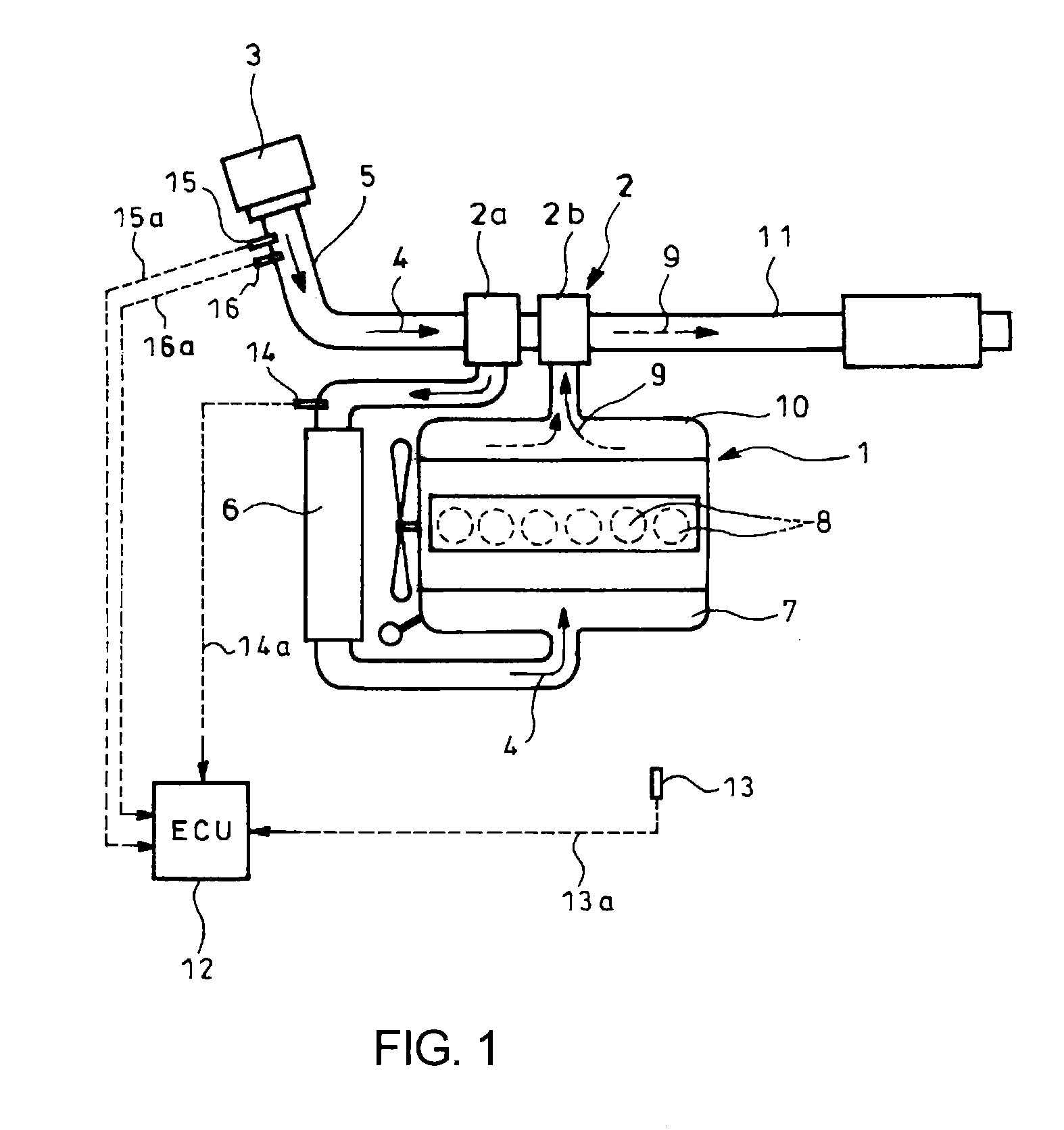
[0025]FIG. 1 shows the embodiment of the invention. In FIG. 1, reference numeral 1 denotes an engine with a turbocharger 2 having a compressor 2a to which fed is intake air 4 from an air cleaner 3 through an intake pipe 5. The intake air 4 thus pressurized in the compressor 2a is fed to an intercooler 6 where it is cooled. The cooled intake air 4 from the intercooler 6 is further guided to an intake manifold 7 and distributed into each of cylinders 8 in the engine 1.

[0026]Exhaust gas 9 discharged from each of the cylinders 8 in the engine 1 is fed via an exhaust manifold 10 to a turbine 2b of the turbocharger 2. The exhaust gas 9 thus having driven the turbine 2b is discharged through an exhaust pipe 11 to outside of the vehicle.

[0027]Further, arranged at an appropriate site in an engine compartment less affected by aerodynamic drag is an atmospheric pressure sensor 13 (first pressure sensor) for...


PUM


Abstract

Based on entry/exit pressures of compressor 2a detected by atmospheric/boost pressure sensors 13 and 14, pressure ratio of compressor is calculated. Based on mass flow rate and entry temperature of intake air 4 detected by intake air flow-rate/temperature sensors 15 and 16 and entry pressure, volumetric flow rate of intake air is calculated in environmental condition at detection time using gas state equation, and is corrected into volumetric flow rate under standard environmental condition thorough multiplication by corrective coefficient based on entry temperature of intake air. Based on corrected value and calculated pressure ratio, rotational frequency of compressor under standard environmental condition is read out in light of operating characteristic diagram for compressor. Read-out rotational frequency is corrected into actual rotational frequency of compressor through multiplication by corrective coefficient based on entry temperature of intake air, which is determined as rotational frequency of turbocharger 2.

Description

TECHNICAL FIELD[0001]The present invention relates to a turbo rotational frequency detection device.BACKGROUND ART[0002]In recent engine designing, a downsizing concept shifted from a conventional concept with a high regard to top performance is becoming mainstream. In progress is changeover to supercharged engines in which engine displacement and a number of cylinders are reduced by supercharging with a turbocharger to obtain an output and a torque equivalent to those of natural intake engines with a size larger than the supercharged ones.[0003]For example, in diesel engines, V-twelve and -eight engines used to be prevailing in particular with respect to commercial vehicles (trucks). Now, supercharged straight-six and -four engines are becoming mainstream owing to the downsizing concept.[0004]In association with such downsizing concept being becoming main stream, further compactification in size of turbochargers has been demanded, which makes it difficult to arrange a rotation sens...

Claims


Application Information

Patent Timeline
IPC IPC(8): G01M15/14
CPCG01M15/14F02B39/16F02B2037/122F02B2039/168F02D41/18F02D41/0007F02D2200/0402F02D2200/0406F02D2200/0414
Inventor NAKANO, HITOSHIIWAMA, HIDEYO
Owner HINO MOTORS LTD
Why Eureka
Try Eureka