Load sensor, load detector including load sensor, and method for detecting load
- Summary
- Abstract
- Description
- Claims
- Application Information
AI Technical Summary
Benefits of technology
Problems solved by technology
Method used
Image

Examples
exemplary embodiment 1
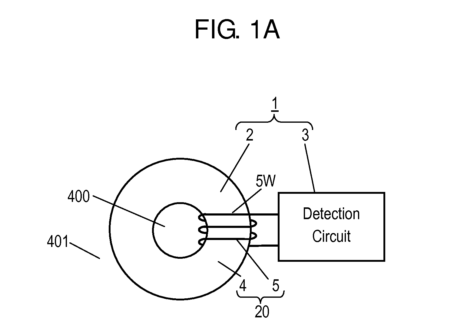
[0064]FIG. 1A is a schematic view of load detector 1 according to Exemplary Embodiment 1. Load detector 1 includes load sensor 2 and detection circuit 3.
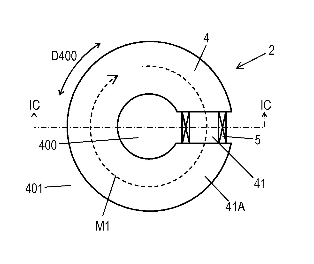
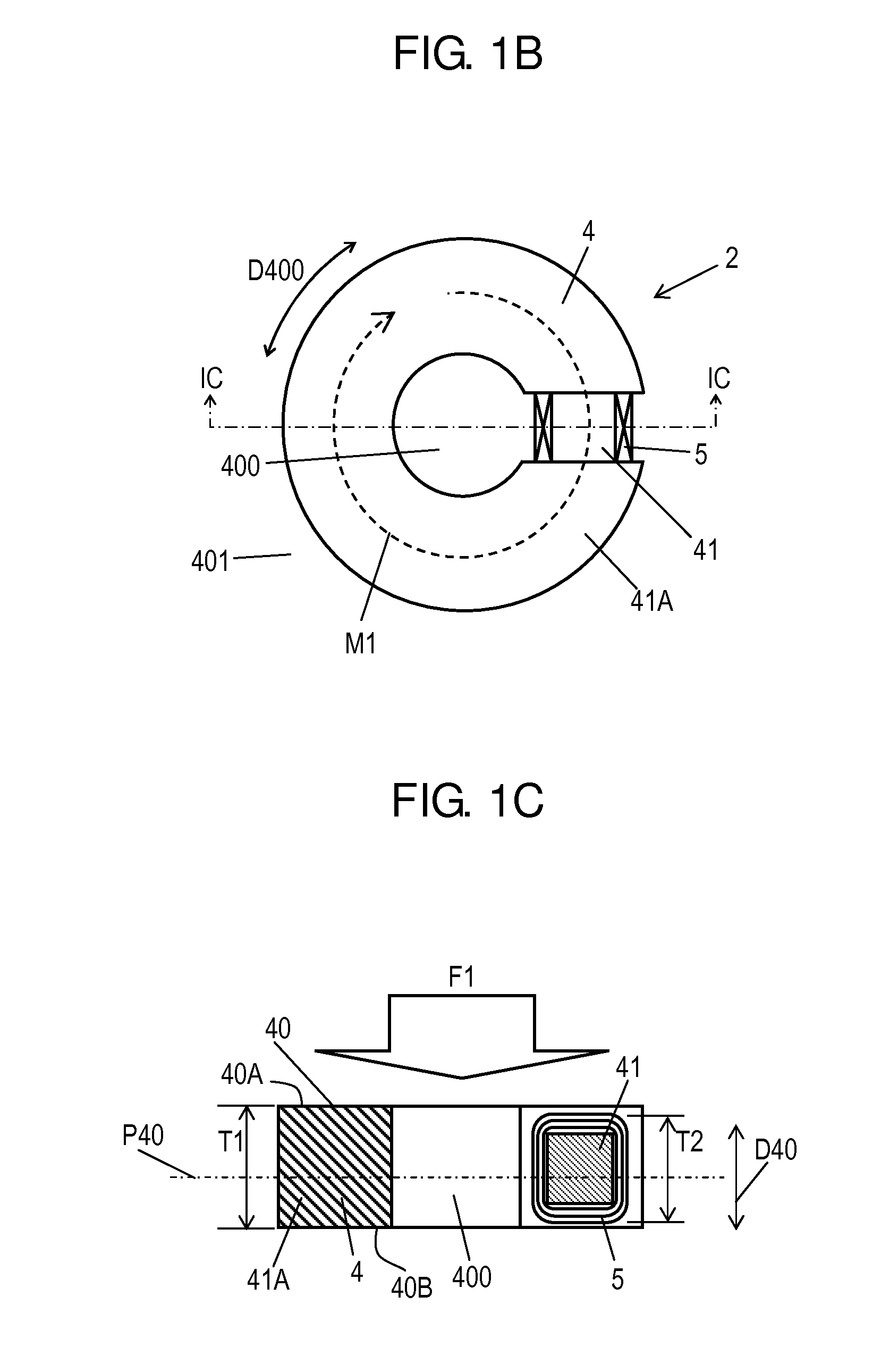
[0065]FIG. 1B is a schematic plan view of load sensor 2. FIG. 1C is a schematic cross-sectional view of load sensor 2 at line IC-IC shown in FIG. 1B. Load sensor 2 includes core 4 made of magnetic material and coil 5 attached to core 4. Core 4 has hollow part 400. Magnetic path M1 along which magnetic flux generated by a current flowing in coil 5 passes is formed along a circumference direction D400 of hollow part 400. Core 4 has load-receiving portion 40 provided at surface 40A of core 40 located in crossing direction D40 crossing a plane having magnetic path M1 formed thereon. Load-receiving portion 40 is configured to receive load F1. Core 4 and coil 5 constitute detecting unit 20 that detects load F1. Core 4 has surface 4B opposite to surface 4A.
[0066]Detection circuit 3 detects the load applied to load-receiving portion 40, bas...
exemplary embodiment 2
[0104]FIG. 13A a schematic view of load detector 1A according to Exemplary Embodiment 2. In FIG. 13A, components identical to those of load detector 1 shown in FIG. 1A according to Embodiment 1 are denoted by the same reference numerals. Load detector 1A includes load sensor 2J instead of load sensor 2 of load detector 1 shown in FIG. 1A according to Embodiment 1.
[0105]FIG. 13B is a plan view of load sensor 2J. FIG. 13C is a cross-sectional view of load sensor 2J at line XIIIC-XIIIC shown in FIG. 13B. In FIGS. 13B and 13C, components identical to those of load sensor 2 shown in FIGS. 1B and 1C according to Embodiment 1 are denoted by the same reference numerals. Load sensor 2J according to Embodiment 2 includes detection unit 20, first plate 21, second plate 22, elastic body 23, and board 24. Detection unit 20 includes core 4 made of magnetic material and coil 5 magnetically coupled to core 4. First plate 21 and second plate 22 are disposed to sandwich detecting unit 20 from both si...
exemplary embodiment 3
[0128]FIG. 16A is a plan view of load sensor 2L according to Exemplary Embodiment 3. FIG. 16B is a cross-sectional view of load sensor 2L at line XVIB-XVIB shown in FIG. 16A. In FIGS. 16A and 16B, components identical to those of load sensor 2J shown in FIGS. 13B and 13C are denoted by the same reference numerals. Load sensor 2L according to Embodiment 3 is used in, for example, a ground anchor construction method.
[0129]The ground anchor construction method will be briefly described below. When an artificial slope is formed by, for example, excavation or embankment of the ground, the ground anchor construction method is generally used to stabilize a structural object provided on the slope. Load sensors and load detectors are used to detect and monitor a tensile load of an anchor used in the ground anchor construction method.
[0130]When load sensors 2 and 2A to 2H according to Embodiment 2 are used in a large device, such as an anchor, core 4 having a large diameter needs to be used a...
PUM
 Abstract
Description
Claims
Application Information
 - R&D
- Intellectual Property
- Life Sciences
- Materials
- Tech Scout
- Unparalleled Data Quality
- Higher Quality Content
- 60% Fewer Hallucinations
Browse by: Latest US Patents, China's latest patents, Technical Efficacy Thesaurus, Application Domain, Technology Topic, Popular Technical Reports.
© 2025 PatSnap. All rights reserved.Legal|Privacy policy|Modern Slavery Act Transparency Statement|Sitemap|About US| Contact US: help@patsnap.com