
LED array primary display light sources employing dynamically switchable bypass circuitry

a technology of bypass circuitry and primary display light source, which is applied in the direction of electric variable regulation, process and machine control, instruments, etc., can solve the problems of short life of electroluminescent systems, high heat output of incandescent illumination systems, so as to achieve easy replacement of burnt elements, low power consumption, and low heat output

Inactive Publication Date: 2002-04-18
IDD AEROSPACE
View PDF0 Cites 205 Cited by
  • Summary
  • Abstract
  • Description
  • Claims
  • Application Information

AI Technical Summary

Benefits of technology

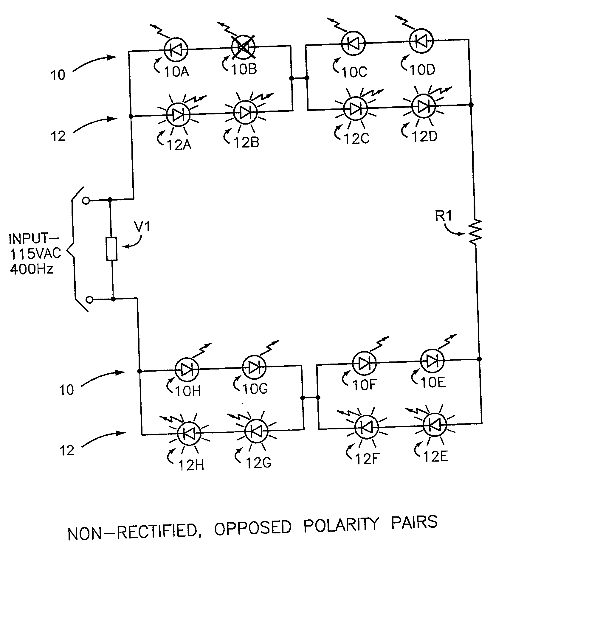
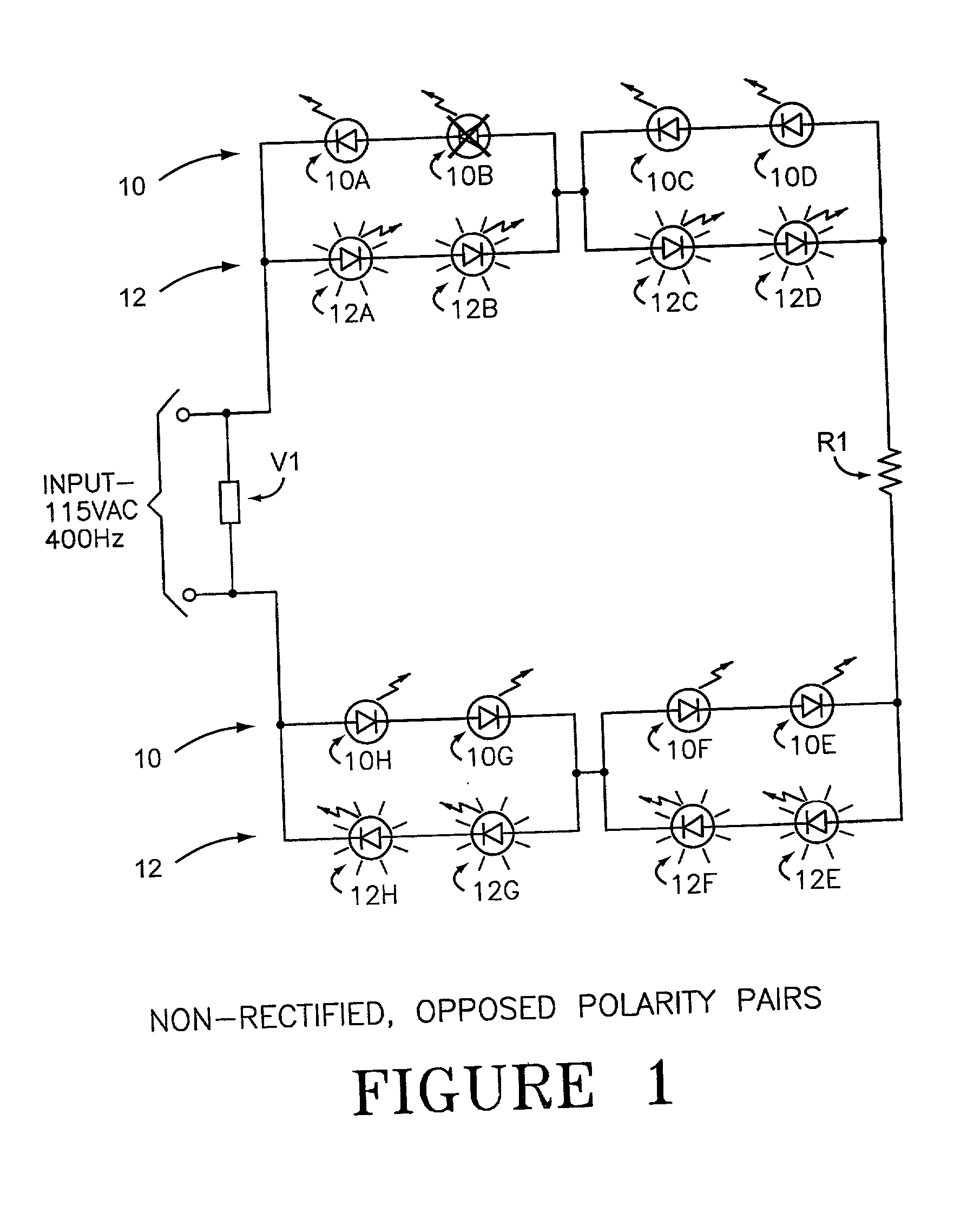
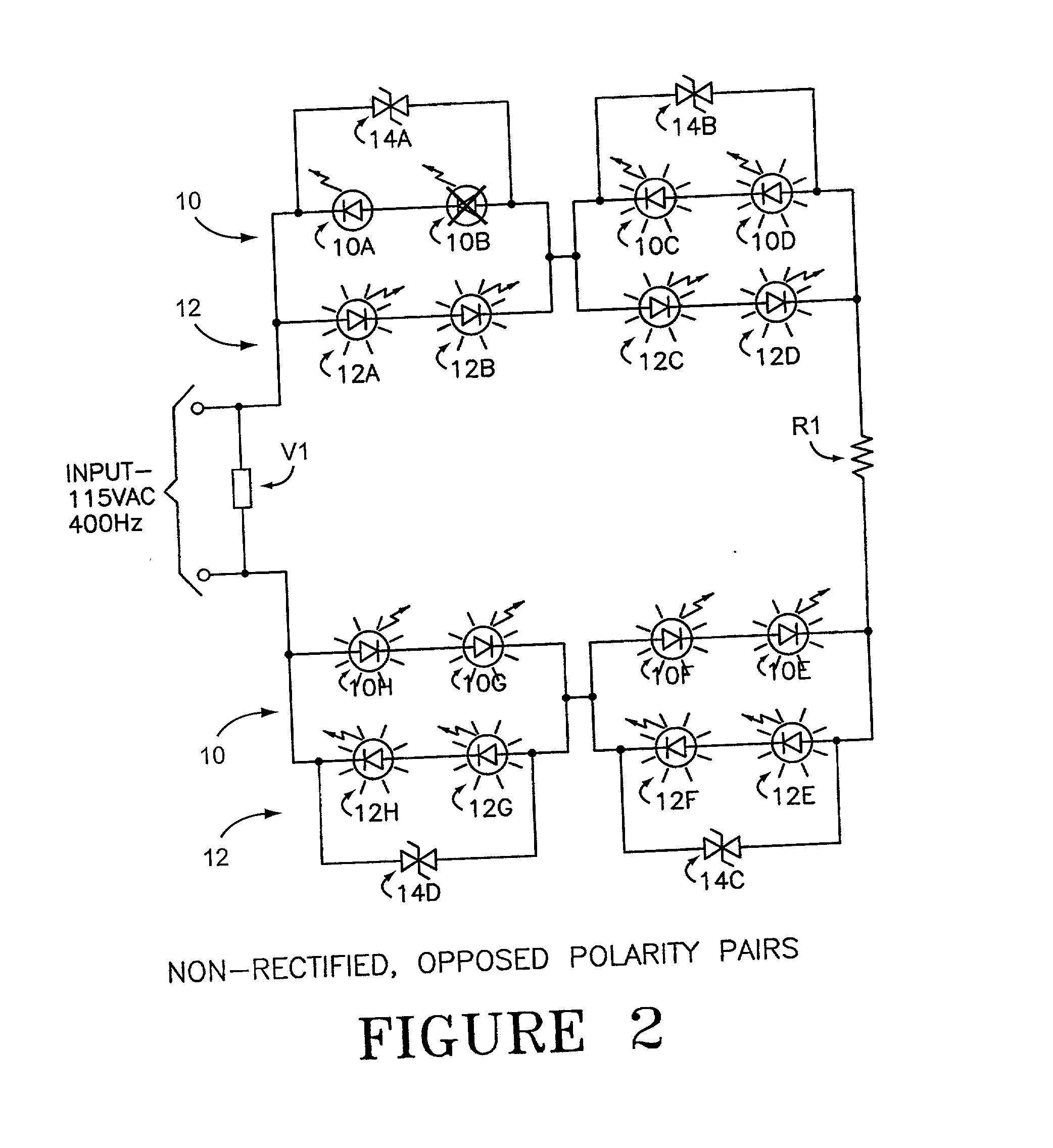
[0014] The invention comprises a circuit design and system that makes possible the use of robust light element arrays in a wide variety of illumination systems where reliability over a long use life, low power consumption, low heat output, resistance to shock, vibration and humidity, and easy burn-out element replacement are important. More particularly, and in the preferred embodiment, the invention comprises the use of one or more DSB devices in parallel to one or more LED light elements to keep the circuits functioning when an LED fails, and to assist in pinpointing which of the LEDs in a string have failed without extensive diagnostic testing or a pull-and-replace empirical repair procedure. While the DSB bypass architecture of the present invention is applicable to both incandescent and LED light elements, the LED / DSB architecture will be discussed in detail by way of illustration of the principles of the invention.

Problems solved by technology

Incandescent illumination systems have a relatively long life, but are sensitive to shocks and vibrations.
Incandescent systems have substantial power requirements and accordingly create a great deal of heat for the light they produce.
Another problem is that the copper leads on circuit boards must be sized appropriately for the power requirements of the circuit, which is several orders of magnitude greater than that of either EL or LED lighting.
Electroluminescent systems have short lives, and typically are susceptible to varying degrees of damage from humidity.
However, they are rugged in terms of shock and vibration.
Further, EL displays experience rapid degradation of brightness over time, such that the "half-life", i.e., the time for the initial brightness to decline to 1 / 2 the original, is on the order of 1000-3000 hours in typical avionics applications.
Although several tricks are employed to extend the life of EL displays, each has its limitations.
Further, there is a power supply mismatch.
That is, the voltage or frequency reductions necessary to achieve a satisfactory life do not match the supply, thus either preventing use of EL displays, or sacrificing life.
In order to run at the lower voltage and frequency, a separate power supply is required, adding cost to the system, and at the cost of lower luminosity.
However, those apparent wiring and simpler balancing advantages of EL displays comes at the cost of EL display humidity sensitivity; the larger the surface area, the more humidity degradation sites can arise.
Often the point of humidity attack is at the site of attachment of the lead, as secure attachment and good, vapor resistant electrical contact with the EL phosphor coating is problematic.
Further, the humidity attack frequently leads to a speckled appearance of brownish or blackish (discolored) spots over large areas of the EL sheet surface, which may be a result of dielectric breakdown.
In the rectified AC circuit, when one LED in a series of LEDs fails, the entire series or string of LEDs fails.
Therefore, while LEDs are rugged and seem ideal for illumination, LEDs traditionally do not make good illumination systems for panels, warning lights, etc. when several LEDs are in series, because they do not provide illumination in their failure mode.
This makes it time consuming to determine which of the LEDs in the failed string has failed, since all black out when only one goes bad.
Silicon TVSs are similar to MOVs, though silicon TVSs clamp faster than MOVs and at lower voltages, but are limited in their surge current levels.

Method used


Image

  • LED array primary display light sources employing dynamically switchable bypass circuitry
  • LED array primary display light sources employing dynamically switchable bypass circuitry
  • LED array primary display light sources employing dynamically switchable bypass circuitry

Examples


Embodiment Construction

[0048] The following detailed description illustrates the invention by way of example, not by way of limitation of the principles of the invention. This description will clearly enable one skilled in the art to make and use the invention, and describes several embodiments, adaptations, variations, alternatives, and uses of the invention, including what are presently believed to be the best modes of carrying out the invention.

[0049] In this regard, the invention is illustrated in the several figures and tables, where applicable, and is of sufficient complexity that the many parts, interrelationships, process steps, and sub-combinations thereof simply cannot be fully illustrated in a single patent-type drawing or table. For clarity and conciseness, several of the schematic diagrams omit parts or steps that are not essential in that drawing to a description of a particular feature, aspect or principle of the invention being disclosed.

[0050] Each of the circuit diagrams included is mere...


PUM


Abstract

The invention comprises use of Dynamically Switchable Bypass (DSB) elements in association with one or more Light Emitting Diodes (LEDs) in arrays for illumination circuits to provide rugged, reliable lighting. The DSBs are selected from Transient Voltage Suppressors, including Silicon, Metal Oxide Varistors, and Multi Layer Varistors as well as Zener Diodes. The DSBs are not used as circuit protecting devices, but rather as alternative paths for electric current to bypass failed LEDs. Bi-directional TVSs are used as alternative electric paths for circuits using Alternating Current (AC) and parallel LED arrays that light on both phases of AC. Zener Diodes are used in parallel to, but in the opposite polarity orientation to, one or more LEDs in DC or rectified AC circuits. The inventive paired DSB / LED elements overcomes the black-out problems of prior series LED illumination systems, making possible the use of robust LEDs in illumination systems where reliability, long life, low power consumption, low heat output, resistance to shock, vibration, and humidity, and self-diagnosis are important. The DSB elements have breakdown voltages slightly higher than the LED(s) they support, so that when an LED fails, the conduction through the DSB begins. Because the conduction voltage of the DSB so nearly matches the conduction voltage of the LED(s), the remainder of the circuit continues to function as normal. The system is self-diagnostic in that any LED failure presents itself as a dark LED rather than as a whole string of dark LEDs. DSBs may be used with incandescent bulbs.

Description

[0001] This application is related to, and claims priority of, Provisional Application Serial No. 60 / 239,414 filed Oct. 10, 2000 under 35 USC .sctn.119.[0002] The invention relates to illumination systems, and more particularly to the use of light elements, particularly Light Emitting Diodes (LEDs), in arrays in conjunction with Dynamically Switchable Bypass (DSB) circuitry to provide rugged reliability. The devices, circuits and systems of the invention show particular utility in aerospace, military, and commercial lighting applications or anywhere panel or display lighting is used.Background of the Art[0003] The background of this invention involves both display light sources and dynamically switchable bypass circuitry.[0004] Display Light Sources:[0005] Display lighting, as distinct from general or area illumination including flood and spot lighting, are used for a variety of purposes including the illumination of panels, instrumentation, warning and directional signals, and the ...

Claims


Application Information

Patent Timeline
IPC IPC(8): H05B37/03H05B44/00
CPCH05B33/0803Y02B20/341H05B37/036H05B33/0821H05B47/23Y02B20/30H05B45/42H05B45/54
Inventor MENZER, RANDY L.DULIN, JACQUES M.
Owner IDD AEROSPACE
Learn More