Flattened Envelope Heat Exchanger

a heat exchanger and envelope technology, applied in indirect heat exchangers, lighting and heating apparatuses, laminated elements, etc., can solve problems such as limited number of viable products

Inactive Publication Date: 2015-05-28
BRAYTON ENERGY
View PDF56 Cites 11 Cited by
  • Summary
  • Abstract
  • Description
  • Claims
  • Application Information

AI Technical Summary

Benefits of technology

[0008]In some embodiments, additional features of the device comprise: the interior fin length is less than the peripheral length, each of the first exterior fin and the second exterior fin form a plurality of longitudinal cavities, the upper and the lower exterior surfaces are parallel and planar, the interior fin is interconnected to at least one of an upper interior surface and a lower interior surface of the peripheral envelope, the interior fin is interconnected to both an upper interior surface and a lower interior surface of the peripheral envelope, the interior fin is interconnected to at least one of an upper interior surface and a lower interior surface of the peripheral envelope by at least one of brazing, soldering and diffusion bonding, the upper and the lower exterior surfaces are interconnected by rounded edges defining the height of the peripheral envelope, the interior fin is configured in a sinusoidal cross-sectional shape forming the plurality of longitudinal cavities, the interior fin is coated with at least one of a braze alloy or a metal melt depressant slurry, the first manifold interconnects to a plurality of unit cell devices, the plurality of unit cell devices stacked upon one another, each of the first exterior fin and the second exterior fin form a plurality of longitudinal cavities, wherein the upper and the lower exterior surfaces are parallel and planar, wherein each of the interior fin and exterior fins are of sinusoidal cross-sectional shape, the device further comprises a first manifold, the first manifold configured to provide a first fluid flow with the interior void and interconnected to the first end, and the device further comprises a second manifold, the second manifold connected to the second end.

Problems solved by technology

However, technical challenges associated with surviving the severe environment of a gas turbine exhaust while meeting the equally severe cost challenges has limited the number of viable products.

Method used


Image

  • Flattened Envelope Heat Exchanger
  • Flattened Envelope Heat Exchanger
  • Flattened Envelope Heat Exchanger

Examples


Embodiment Construction

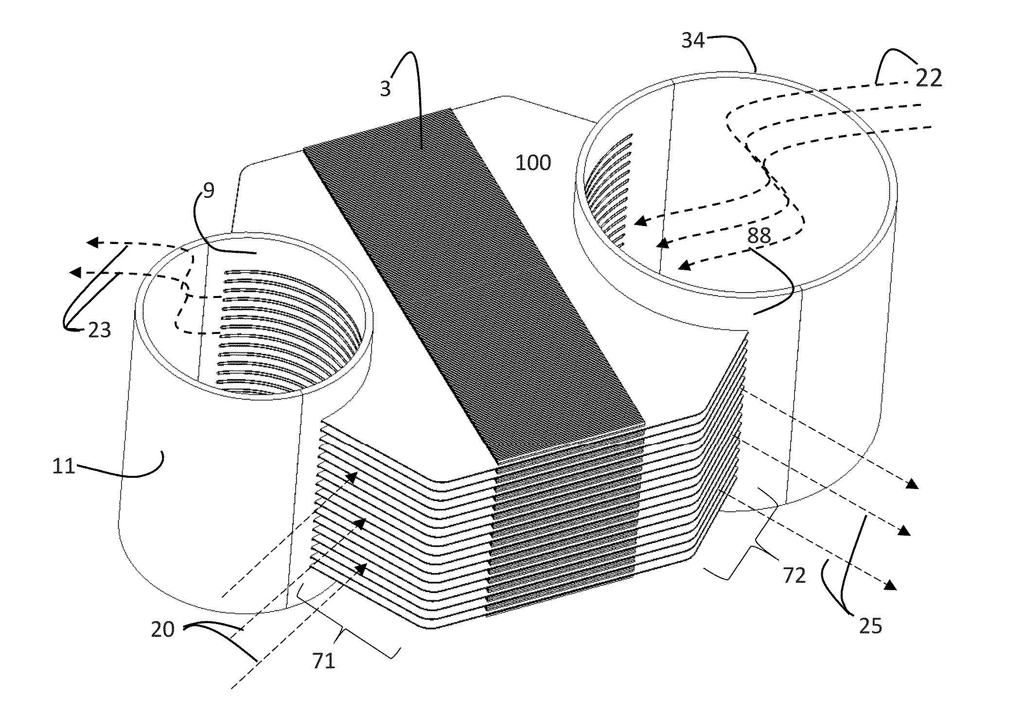
[0026]Generally, embodiments of the unit cell are provided in FIGS. 1-4, 10-11, 15-16, and 20-21. Embodiments of the unit cell as engaged with a manifold are provided in FIGS. 5-9 and 12-14. FIGS. 17-19 depict method of manufacturing features.

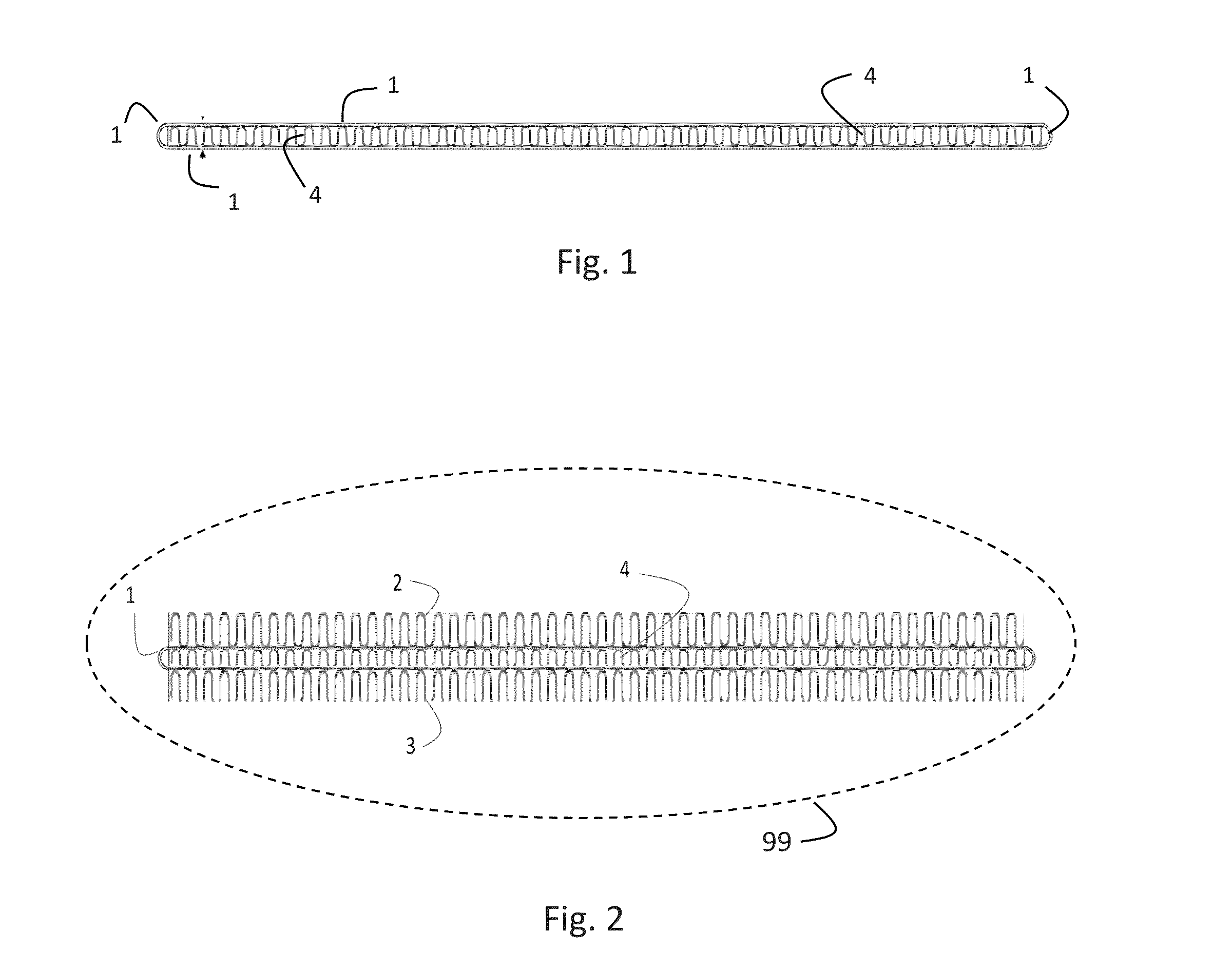
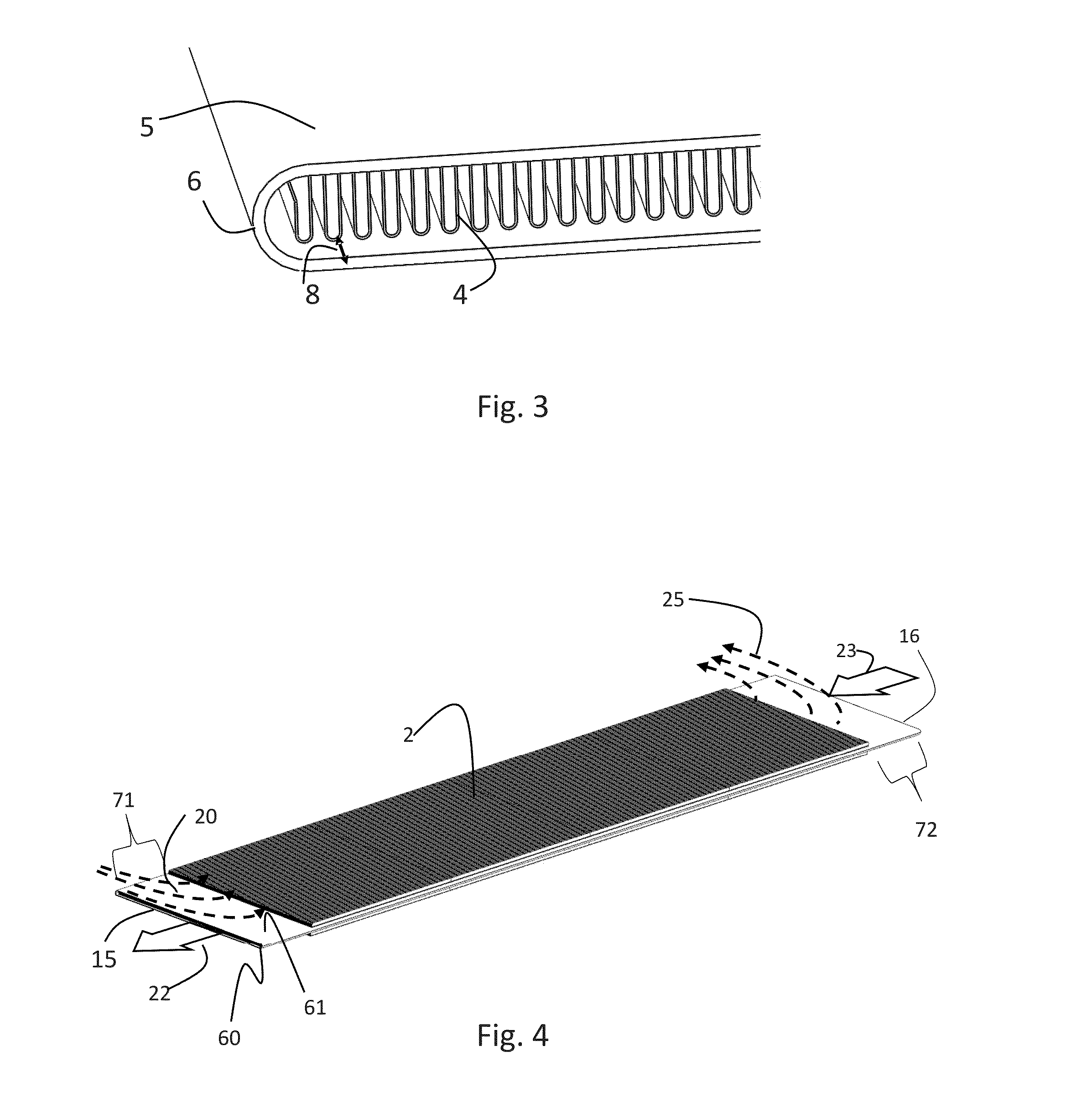
[0027]With respect to FIGS. 1-21, a unit cell 99 comprises an envelope 1, an interior or internal fin 4, an upper or first external fin 2 and a lower or second exterior fin 3. FIG. 1 provides an illustration of the flattened envelope 1 in cross-sectional view. The envelope's perimeter is a continuous sheet. The flattened envelope forms a closed interior volume or void, with exposed first (top), second (bottom) exterior surfaces, and a third (top) interior surface, and a fourth (bottom) exterior surface. Internal fin 4 is sandwiched between the third and fourth interior surfaces and bonded to the interior surfaces by any of several methods known to those skilled in the art, to include brazing, diffusion bonding, soldering, sintered, or otherwise...


PUM

PropertyMeasurementUnit
temperaturesaaaaaaaaaa
pressuresaaaaaaaaaa

Abstract

The present invention provides an apparatus and method for heat exchange. Embodiments of the present invention include a method and apparatus for heat exchange employing a unit cell using interior and exterior fins, the interior fins disposed within a flattened envelope structure. In one particular embodiment, the heat exchanger is directed for use as a gas engine recuperator.

Description

CROSS REFERENCE TO RELATED APPLICATIONS[0001]This application claims the benefit of U.S. Provisional Patent Application No. 61 / 909,492 entitled “Flattened Envelope Heat Exchanger” filed on Nov. 27, 2014, the entire disclosure of which is incorporated by reference herein. This application cross-references U.S. Provisional Patent Application Nos. 61 / 778,742 filed Mar. 13, 2013, and 61 / 809,931 filed Apr. 9, 2013.FIELD[0002]Embodiments of the present invention are generally related to a method and apparatus for heat exchange, and in particular, to a method and apparatus for heat exchange employing a unit cell using interior and exterior fins, the interior fins disposed within a flattened envelope structure. In one particular embodiment, the heat exchanger is directed for use as a gas engine recuperator.BACKGROUND[0003]The recuperation of the gas turbine engine is a proven method for increasing thermal efficiency. However, technical challenges associated with surviving the severe environ...

Claims


Application Information

Patent Timeline
Patent Type & Authority Applications(United States)
IPC IPC(8): F28F3/04B23P15/26
CPCB23P15/26F28F3/04F28D1/05383F28F3/025Y10T29/4935
Inventor NASH, JAMES S.
Owner BRAYTON ENERGY
Why Eureka
Try Eureka