

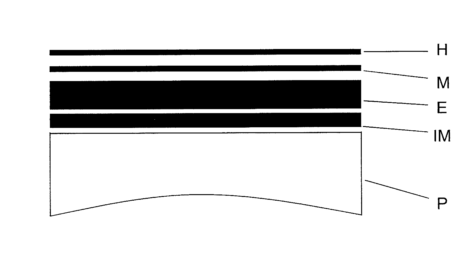
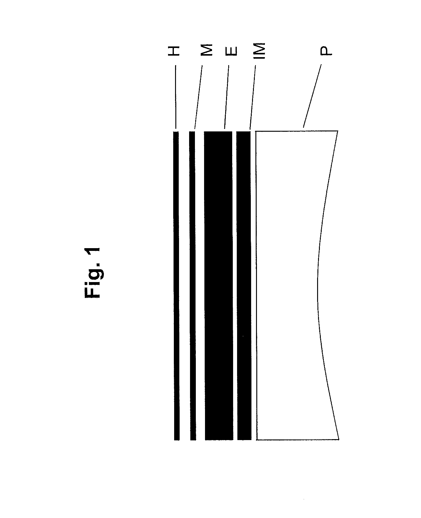
Ophthalmic lens comprising a base of polymeric material with a coating having an interferential, Anti-reflective, Anti-iridescent and ir filter multiple layer structure
a polymeric material and multiple layer structure technology, applied in the field of ophthalmic lenses, can solve the problems of difficult application of transparent lenses without colouring, complex solutions for ir light filtering, and inability to obtain high visible transmittance lenses with these features, so as to improve the effect of ira radiation filtering and improve the transmittance of visible ligh
- Summary
- Abstract
- Description
- Claims
- Application Information
AI Technical Summary
Benefits of technology
Problems solved by technology
Method used
Image

Examples
example 1
Minimising the Reflection of Visible Radiation
[0072]
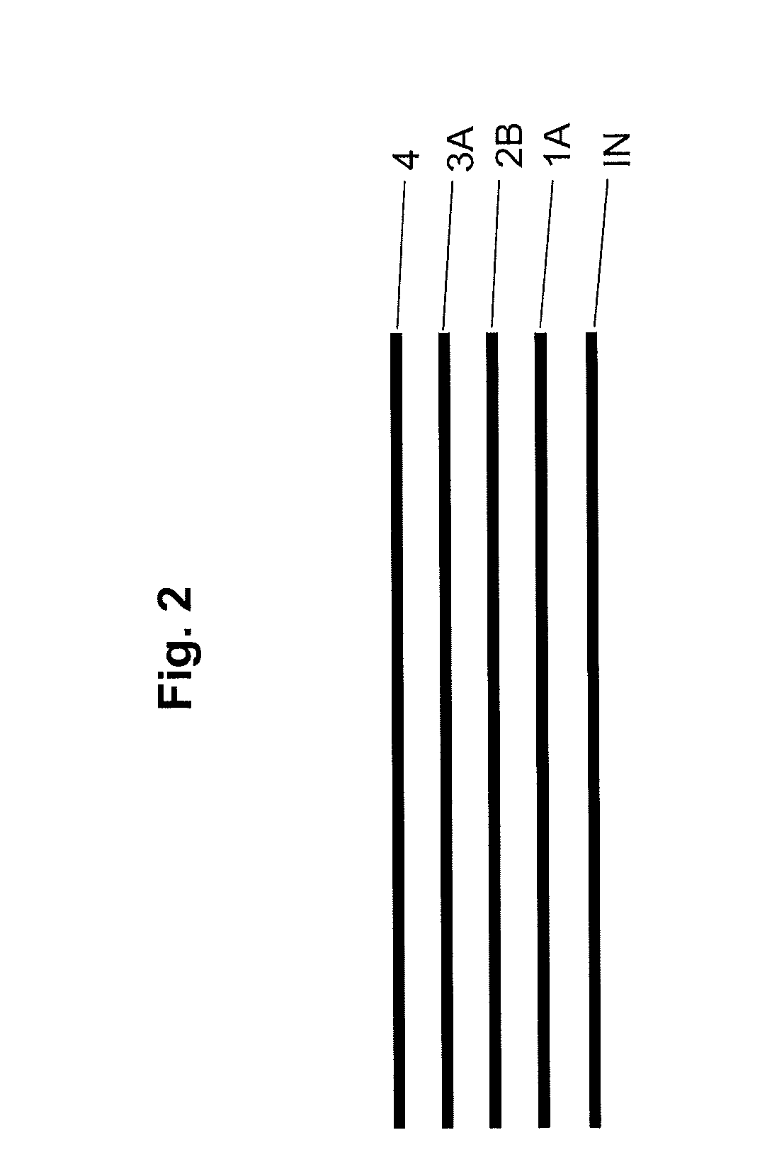
Layer 4SiO2-81.2 nmLayer 3ATiO2-101.8 nmLayer 2BSiO2-169.9 nmLayer1ATiO2-120.8 nmBasePolymer nD = 1.6RV 15° 0.5%RV 60° 5.0%T IR-A71.8%Total thickness437.7 nm
[0073]FIG. 3 shows a graph showing the reflection (in %) according to the wave length (λ, in nm) of the incident radiation.
example 2
Minimising the Transmission of IR-A Radiation
[0074]
Layer 4SiO2-61.4 nmLayer 3ATiO2-107.6 nmLayer 2BSiO2-169.0 nmLayer 1ATiO2-126.0 nmBasePolymer nD = 1.6RV 15° 1.5%RV 60° 5.0%T IR-A69.7%Total thickness463.9 nm
[0075]FIG. 4 shows a graph showing the reflection (in %) according to the wave length (λ, in nm) of the incident radiation.
example 3
Minimising the Reflection of Radiation at 60°
[0076]
Layer 4SiO2-98.0 nmLayer 3ATiO2-117.7 nmLayer 2BSiO2-202.3 nmLayer 1ATiO2-129.9 nmBasePolymer nD = 1.6RV 15° 1.5%RV 60° 3.0%T IR-A75.3%Total thickness547.8 nm
[0077]FIG. 5 shows a graph showing the reflection (in %) according to the wave length (λ, in nm) of the incident radiation.
PUM
| Property | Measurement | Unit |
|---|---|---|
| thickness | aaaaa | aaaaa |
| thickness | aaaaa | aaaaa |
| thickness | aaaaa | aaaaa |
Abstract
Description
Claims
Application Information