

Technical or decorative piece associating a transparent material and a silicon based amorphous material and method of manufacturing the same
a technology of amorphous materials and transparent materials, which is applied in the field of decorative pieces associating transparent materials and silicon based amorphous materials and manufacturing methods, and can solve the problems that prior art does not allow the creation of shades of colour at the surface of the dial either
- Summary
- Abstract
- Description
- Claims
- Application Information
AI Technical Summary
Benefits of technology
Problems solved by technology
Method used
Image

Examples
first embodiment
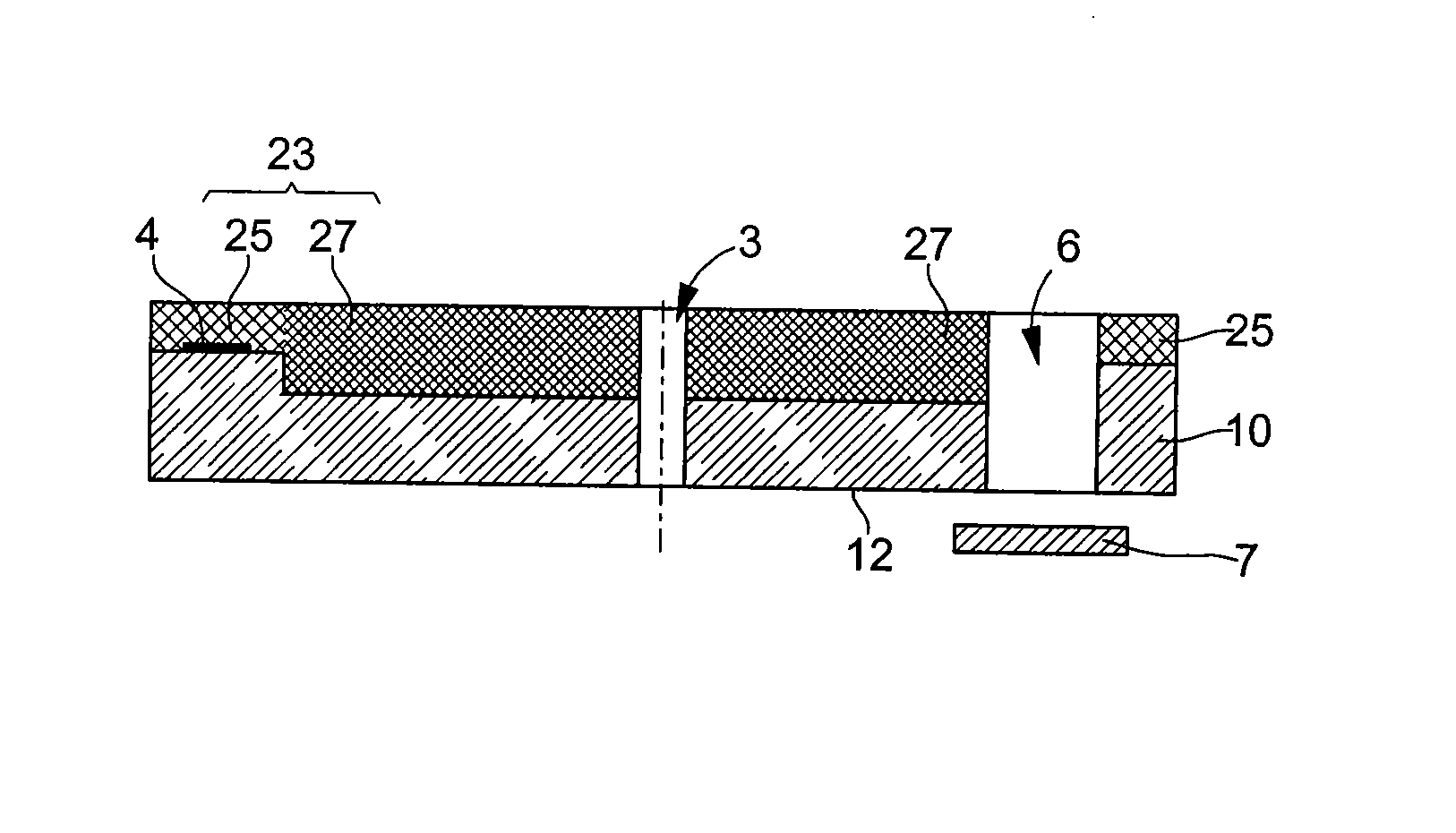
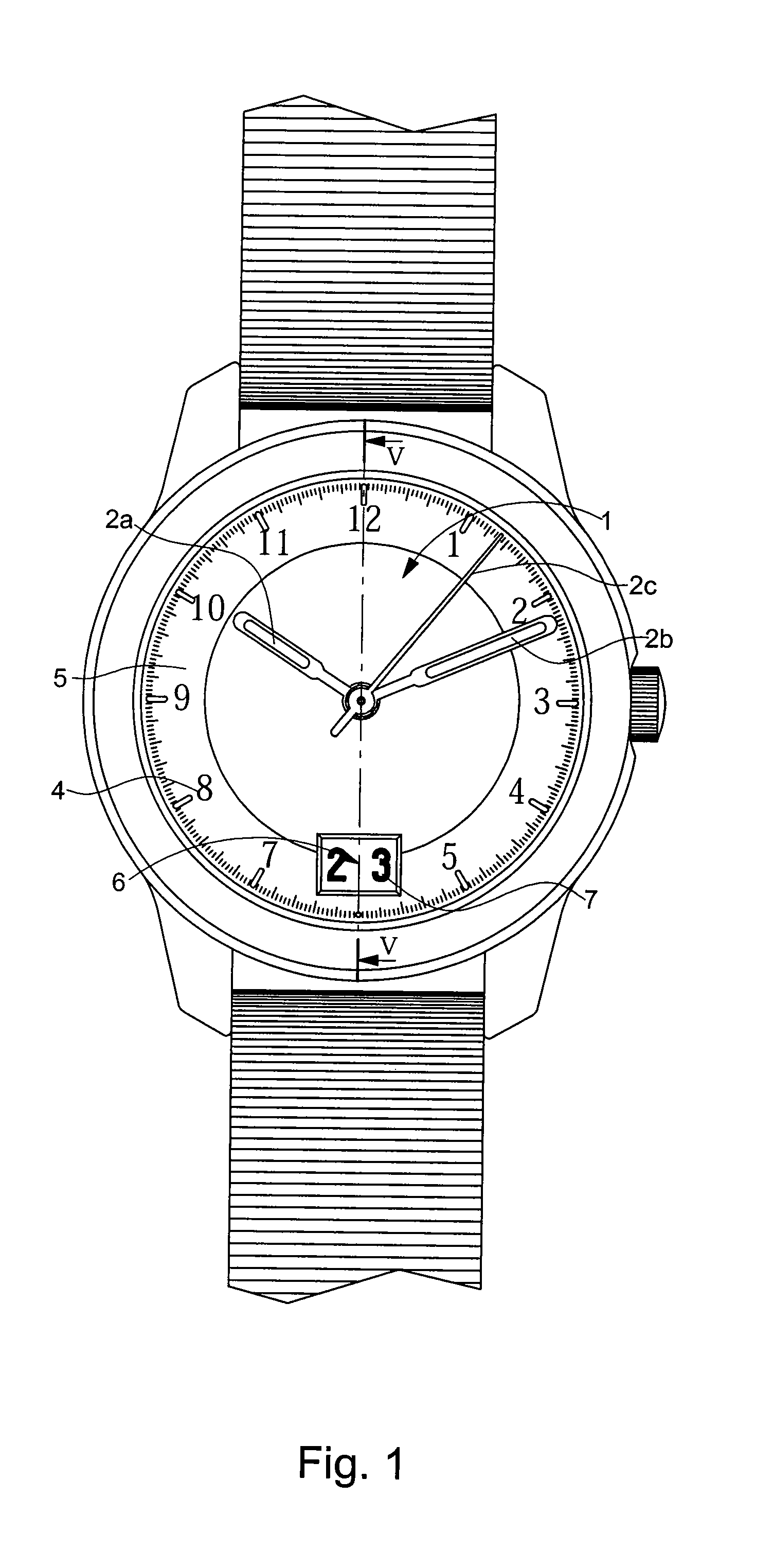
[0018]With reference first of all to FIGS. 1 to 5, a piece according to the invention will be described used to form the dial 1 of a wristwatch with an analogue display by means of hour hand 2a, minute hand 2b and second hand 2c moving opposite hour symbols 4 marked on an hour circle 5. In the example shown, dial 1 includes an aperture 6 passing through the entire thickness of dial 1 and below which there moves a date disc 7.
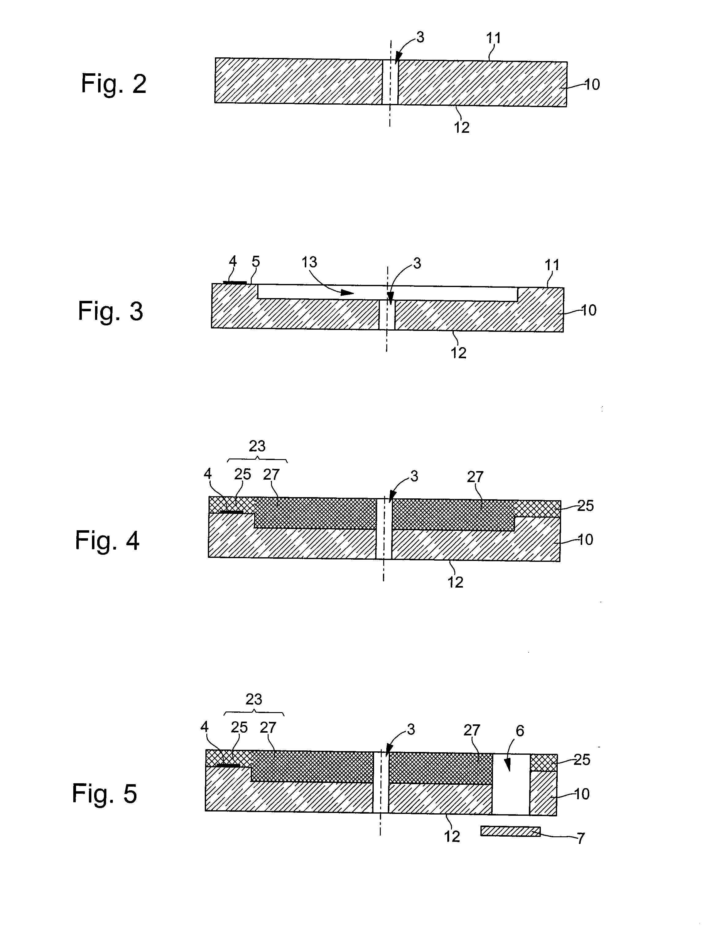
[0019]Dial 1 is shown in cross-section in FIG. 4 along the 6 o'clock-12 o'clock line, the scale along the thickness being greatly exaggerated for better comprehension of the drawings. The dial is formed by a transparent substrate 10 having a top face 11 oriented towards an observer, the bottom face being designated by the reference 12.
[0020]Transparent substrate 10 shown in FIG. 2 is cut to the dimensions of the dial in a plate whose thickness is comprised between 0.4 and 0.9 mm, the material forming said plate being able to resist temperatures higher than 500° ...
second embodiment
[0026]With reference now to FIG. 6, a second embodiment is shown in cross-section, which differs from the preceding embodiment in that the transparent monocrystalline substrate 10 is machined on face 12 opposite the face directly visible to an observer. Zones 14 are machined hollow and filled with enamel layers to form a thick opaque layer 24 that does not exceed the hollow machined parts, thus leaving zones 20 free of any enamel coating and thus totally transparent. The contour of these transparent zones 20 can be such that a part of the mechanism, such as a tourbillon schematically represented by the reference 8, is visible.
[0027]FIG. 7 shows a third embodiment which is a kind of synthesis of the previously described embodiments and which includes back lighting symbolised by an electroluminescent sheet 9. the top face 11 oriented towards an observer, is machined hollow to allow the deposition of thin enamel layers 25 and the deposition of ultra-thin enamel layers 29, for example 0...
fourth embodiment
[0028]For better comprehension of the drawings, the thin and ultra thin enamel depositions have been shown with a constant thickness, i.e. with recesses having a bottom parallel to the surfaces of transparent substrate 10. It is clear that there is no technical difficulty in making the bottoms of the recesses with an inclined surface that gradually varies the thickness of the enamel layers. This embodiment, which is not shown, allows hues of the same colour or a gradual change between two different colours when enamel depositions are carried out on both faces of the transparent substrate and have overlapping zones. Likewise, and particularly when one face includes disjointed recesses, it is possible to have more than one enamel colour on the same face, or to create a partitioned enamelled area. FIG. 8 illustrates a fourth embodiment, which can also be combined with the preceding embodiments. In this embodiment, one of the surfaces, top surface 11, has laser structuring 21 forming a ...
PUM
| Property | Measurement | Unit |
|---|---|---|
| temperature | aaaaa | aaaaa |
| temperature | aaaaa | aaaaa |
| temperatures | aaaaa | aaaaa |
Abstract
Description
Claims
Application Information