Process of debundling carbon fiber tow and molding compositions containing such fibers

a technology of carbon fiber and tow, which is applied in the field of debundling carbon fiber tow, can solve the problems of limited success in the debundling of carbon fiber tow at production scale, and achieve the effect of improving the dispersion of carbon fiber

Active Publication Date: 2015-05-28
TEIJIN AUTOMOTIVE TECH INC
View PDF3 Cites 15 Cited by
  • Summary
  • Abstract
  • Description
  • Claims
  • Application Information

AI Technical Summary

Benefits of technology

[0005]An improved device and method for debundling a large number of carbon fibers collectively forming a tow into dispersed chopped carbon fibers suitable for usage in molding composition formulations is provided. According to an embodiment of the present invention, a carbon fiber tow is fed into a die having fluid flow openings, through which a fluid impinges upon the side of the tow to expand the tow cross sectional area. The expanded cross sectional area tow extends from the die into the path of a conventional fiber chopping apparatus to form chopped carbon fibers. Through adjustment of the relative position of fluid flow openings relative to a die bore through which fiber tow passes, the nature of the fluid impinging on the tow, the shape of the bore, in combinations thereof, an improved chopped carbon fiber dispersion is achieved, compared to existing processes. The chopped carbon fiber obtained according to the present invention is then available in certain embodiments to be dispersed in molding composition formulations prior to formulation cure. Through control of the molding composition monomer polarity, still further dispersion and anisotropy of the chopped carbon fibers is obtained.

Problems solved by technology

However, this effort has met with limited success owing to differences between glass and carbon fibers.
While the debundling of carbon fiber tows is addressed in laboratory scale moldings through manual manipulation, problems exist for production scale debundling of carbon fiber tow into separate chopped carbon fibers.

Method used


Image

  • Process of debundling carbon fiber tow and molding compositions containing such fibers
  • Process of debundling carbon fiber tow and molding compositions containing such fibers
  • Process of debundling carbon fiber tow and molding compositions containing such fibers

Examples


Embodiment Construction

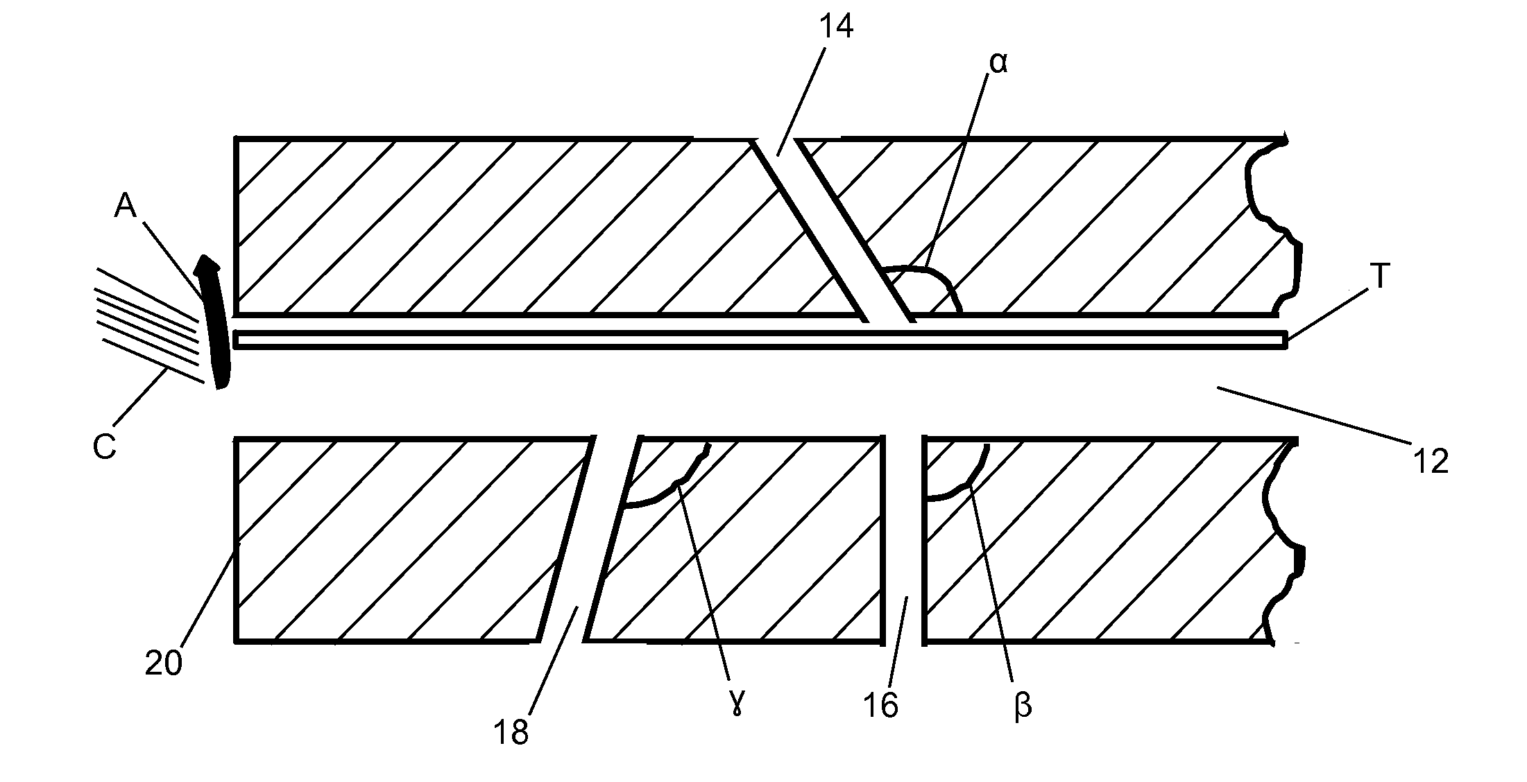
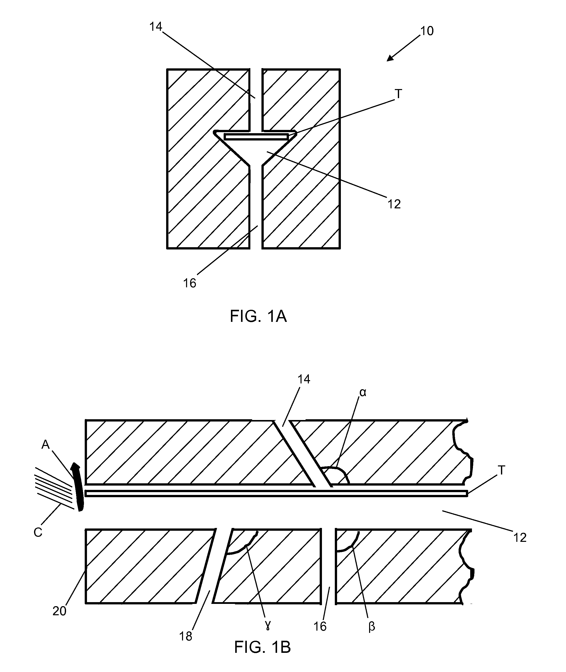
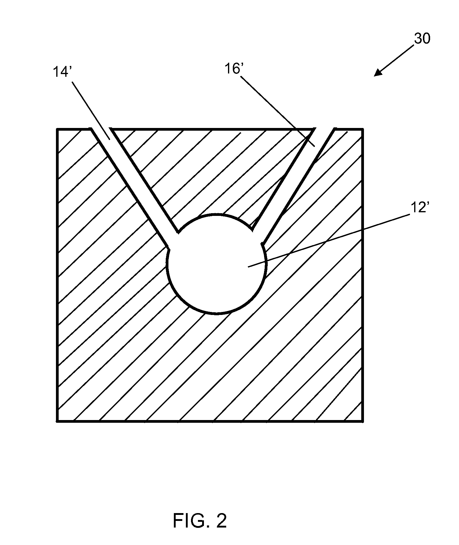
[0013]The present invention has utility in debundling a large number of carbon fibers collectively forming a tow into dispersed chopped carbon fibers suitable for usage in molding composition formulations. According to the present invention, a carbon fiber tow is fed into a die having fluid flow openings, through which a fluid impinges upon the side of the tow to expand the tow cross sectional area. The expanded cross sectional area tow extends from the die into the path of a conventional fiber chopping apparatus to form chopped carbon fibers. Through adjustment of the relative position of fluid flow openings relative to a die bore through which fiber tow passes, the nature of the fluid impinging on the tow, the shape of the bore, in combinations thereof, an improved chopped carbon fiber dispersion is achieved, compared to existing processes. The chopped carbon fiber obtained according to the present invention is then available in certain embodiments to be dispersed in molding compo...


PUM

PropertyMeasurementUnit
diametersaaaaaaaaaa
diametersaaaaaaaaaa
diametersaaaaaaaaaa

Abstract

A process for debundling a carbon fiber tow into dispersed chopped carbon fibers suitable for usage in molding composition formulations is provided. A carbon fiber tow is fed into a die having fluid flow openings, through which a fluid impinges upon the side of the tow to expand the tow cross sectional area. The expanded cross sectional area tow extends from the die into the path of a conventional fiber chopping apparatus to form chopped carbon fibers, or through contacting tines of a mechanical debundler. Through adjustment of the relative position of fluid flow openings relative to a die bore through which fiber tow passes, the nature of the fluid impinging on the tow, the shape of the bore, in combinations thereof an improved chopped carbon fiber dispersion is achieved. The chopped carbon fiber obtained is then available to be dispersed in molding composition formulations prior to formulation cure.

Description

CROSS-REFERENCE TO RELATED APPLICATION[0001]This application claims priority of U.S. Provisional Patent Application Ser. No. 61 / 641,136 filed May 1, 2012, which is incorporated herein by reference.FIELD OF THE INVENTION[0002]The present invention in general relates to a process for debundling carbon fiber tow and in particular, to a process for producing chopped and disbursed carbon fibers amenable to inclusion molding compositions.BACKGROUND OF THE INVENTION[0003]The use of fiber inclusions to strengthen a matrix is well known to the art. Well established mechanisms for the strengthening include slowing and elongating the path of crack propagation through the matrix, as well as energy distribution associated with pulling a fiber free from the surrounding matrix material. In the context of sheet molding composition (SMC) formulations and bulk molding composition (BMC) formulations; hereafter referred to collectively as “molding compositions”, fiber strengthening has traditionally in...

Claims


Application Information

Patent Timeline
Patent Type & Authority Applications(United States)
IPC IPC(8): D02J1/18B32B17/00B29B15/08B32B17/06D01G1/04C08J5/24B32B9/04
CPCD02J1/18C08J5/24B32B17/00B32B9/047B32B17/067B29K2307/04B29B15/08C08J2300/00B32B2250/02B32B2262/101B32B2262/10D01G1/04B29C70/08B65H51/005B65H2701/314B32B5/26B32B2262/106Y10T428/2495Y10T29/49801Y10T83/0405Y10T83/041Y10T83/0443C08J5/04
Inventor GUHA, PROBIR KUMARSIWAJEK, MICHAEL J.HILTUNEN, MICHAEL J.SKOP, SHANEHILTUNENE, CHRISTOPHER
Owner TEIJIN AUTOMOTIVE TECH INC
Why Eureka
Try Eureka