Patient interface device

a patient interface and mask technology, applied in the field of patient interface devices, can solve the problems of difficult design of single masks that fit a large part of the population, user adjustment of such masks, obstruct breathing during sleep, etc., and achieve the effect of avoiding red marks and skin damage, and good sealing properties of patient interface devices

Inactive Publication Date: 2015-06-04
KONINKLJIJKE PHILIPS NV
View PDF9 Cites 2 Cited by
  • Summary
  • Abstract
  • Description
  • Claims
  • Application Information

AI Technical Summary

Benefits of technology

[0029]Even if the force limitation unit is described in the context of a patient interface device, it shall be understood that the force limitation unit can also be applied in any other type of a mask worn by a person. The application of the force limitation unit avoids red marks and skin damage on a person's face and at the same time provides good sealing properties of the patient interface device.

Problems solved by technology

The human airway is composed of walls of soft tissue which can collapse and thereby obstruct breathing during sleep.
A problem facing the design of these masks is the wide variety of shapes and forms present in the human race, which makes it difficult to design a single mask that fits a large part of the population.
A disadvantage of most of the well-known adjustment mechanisms is the fact that the user of such a mask is adjusting the force that the mask exerts on the face by him or herself.
Being generally not an expert in those matters the masks are often either put on with too high a force or too low a force.
Too high a force may easily cause discomfort, leave visually very distractive red marks or even cause skin damage and significant pain.
Too low a force may cause air leaks, defeating the purpose of the pressure support system, and cause a skin discomfort as well as waking-up sleeping patients due to unpleasant noises.
Additionally, the air can also leak into the patient's eyes, causing eye irritation.
The above described problems reduce the patient tolerance and compliance with the medical procedures utilizing the mask.

Method used


Image

  • Patient interface device
  • Patient interface device
  • Patient interface device

Examples


first embodiment

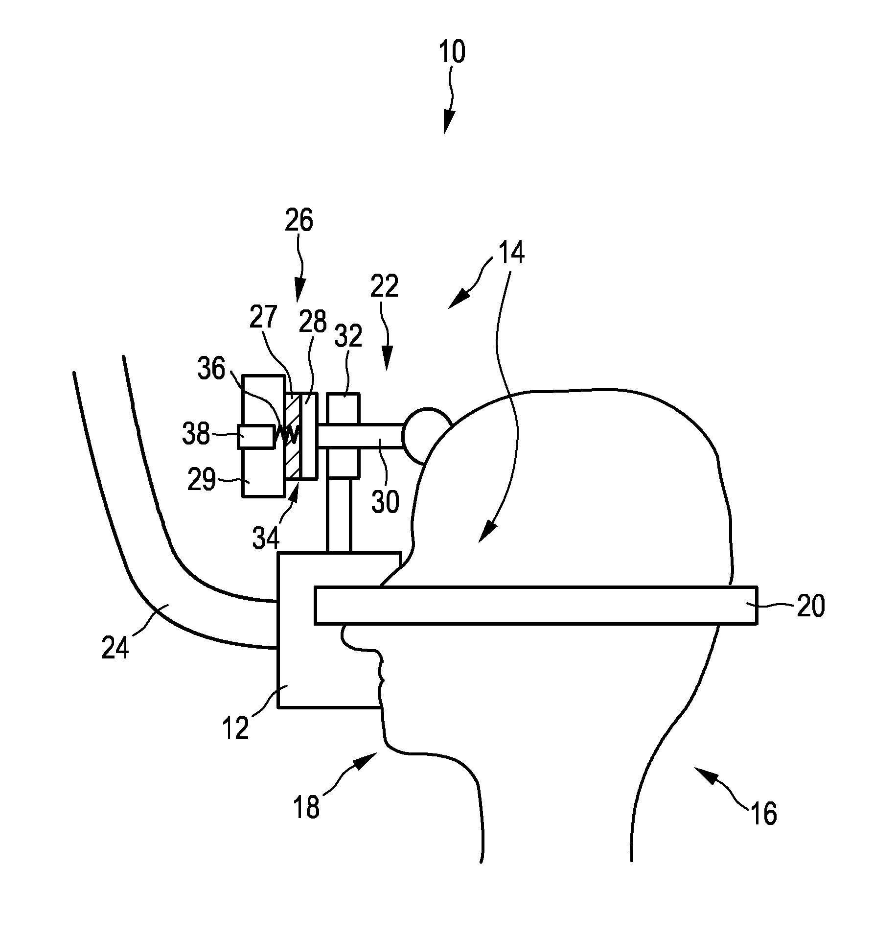
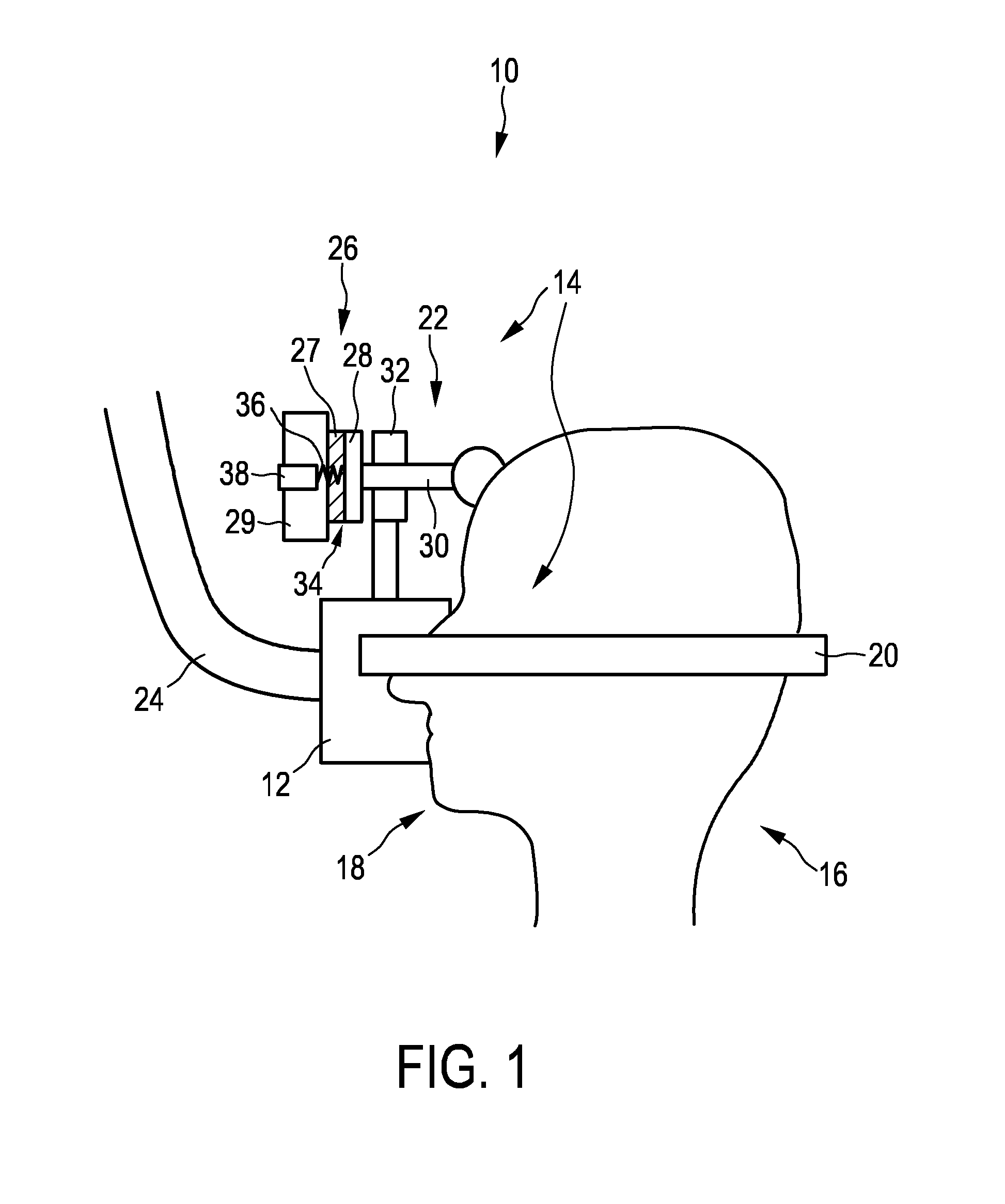
[0034]FIG. 1 shows a patient interface device 10. The patient interface device 10 can, for example, be used in the treatment of Obstructive Sleep Apnea (OSA). The patient interface device 10 comprises a sealing assembly 12 and an attachment assembly 14. The sealing assembly 12 is typically covering the nose and mouth of a patient 16 and delivers a flow of breathable gas to the patient 16. Alternatively, it is also possible that the sealing assembly 12 covers the entire face or only the nose of the patient 16. In another alternative embodiment, the sealing assembly 12 can also comprise cannulas or pillows that are inserted into the nose of the patient 16.

[0035]The sealing assembly 12 is attached to a patient's face 18 using the attachment assembly 14. In this embodiment the attachment assembly 14 comprises headgear straps 20 and a forehead support 22. The headgear straps 20 are providing a flexible force between the head of the patient 16 and the sealing assembly 12 and the forehead ...

second embodiment

[0043]With slip couplings the friction force is provided by a mechanical load between two plates and surfaces respectively. This can be achieved, for example by springs. An alternative way to create the load would be to use magnetic or electromagnetic forces. One embodiment would be to change the preload on the plates by magnetic means (known as electromagnetic clutch). A second embodiment would be to use the magnetic forces directly without the necessity of two plates touching each other in order to provide the coupling. Yet another way to create the load would involve hydraulic forces. In this embodiment pumps and valves would provide control means for such a coupling. The fluids involved in this embodiment could further be modified using electric or magnetic means (e.g. electro-rheological or magneto-rheological fluids).

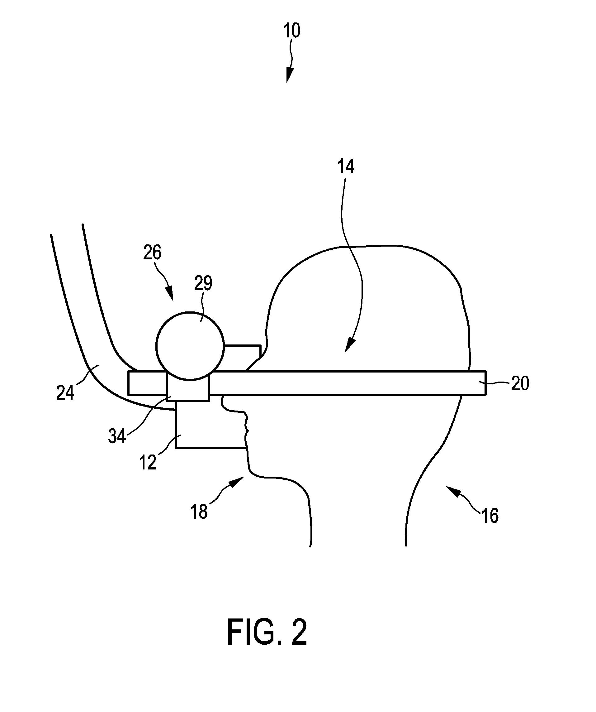
[0044]FIG. 2 shows another embodiment of the patient interface device 10. In the following only the differences in respect to FIG. 1 are described. Same reference...


PUM


Abstract

The present invention relates to a patient interface device (10) comprising a sealing assembly (12) for delivering a flow of breathable gas to a patient (16),an attachment assembly (14) for attaching the sealing assembly (12) to a patient's face (18) and a force limitation unit (26)for limiting a force between the patient interface device(10) and the patient's face (18) to a maximum force when the patient interface device (10) is applied to the patient (16), the force limitation unit (26) comprising a first and a second coupling element (27, 28) constituting a self-releasing force-fitted coupling for transmitting the force from the first to the second coupling element (27, 28) and for interrupting the force-fit between said two coupling elements (27, 28) when the force exceeds the maximum force.

Description

FIELD OF THE INVENTION[0001]The present invention relates to a patient interface device comprising a sealing assembly for delivering a flow of breathable gas to a patient and an attachment assembly for attaching the sealing assembly to a patient's face.BACKGROUND OF THE INVENTION[0002]More and more patients suffer from obstructive sleep apnea or obstructive sleep apnea syndrome (OSA). OSA is usually caused by an obstruction of the upper airway. It is characterized by repetitive pauses in breathing during sleep and is usually associated with a reduction in blood oxygen saturation. These pauses in breathing, called apneas, typically last 20 to 40 seconds. The obstruction of the upper airway is usually caused by reduced muscle tonus of the body that occurs during sleep. The human airway is composed of walls of soft tissue which can collapse and thereby obstruct breathing during sleep. Tongue tissue moves towards the back of the throat during sleep and thereby blocks the air passages. O...

Claims


Application Information

Patent Timeline
Patent Type & Authority Applications(United States)
IPC IPC(8): A61M16/06A61M16/00
CPCA61M16/0622A61M16/0003A61M2205/332A61M16/0683A61M16/0644A61M16/06F16D7/00F16D7/025A61M16/0633A61M16/0638
Inventor DOBRUSSKIN, CHRISTOPHPASTOOR, SANDER THEODOOR
Owner KONINKLJIJKE PHILIPS NV
Why Eureka
Try Eureka