Drive device for vehicle

a technology for driving devices and vehicles, applied in the direction of propulsion parts, propulsion using engine-driven generators, transportation and packaging, etc., to achieve the effect of reducing manufacturing costs and improving reliability of in-gear operation

Active Publication Date: 2015-06-04
HONDA MOTOR CO LTD
View PDF3 Cites 2 Cited by
  • Summary
  • Abstract
  • Description
  • Claims
  • Application Information

AI Technical Summary

Benefits of technology

[0007]It is an object of the present invention to provide a drive device for a vehicle, which is capable of improving reliability of an in-gear operation for switching a speed position on a shaft having an electric motor connected thereto, to an in-gear state, while ensuring a degree of freedom in design of the drive device and realizing reduction of manufacturing costs thereof.
[0009]According to this drive device for a vehicle, the first clutch, the first synchronizer, the second clutch, and the second synchronizer are controlled, and the first synchronizer is controlled such that the two synchronization objects of one of the plurality of first speed positions are connected to each other when the predetermined transmission condition is satisfied which is a condition for transmitting the motive power of the engine to the driven parts via the one first speed position. Further, in the case where the predetermined transmission condition is satisfied, if the detected output rotational speed is not within the predetermined very low speed range, the rotational speed of the electric motor is controlled based on the detected first rotational speed and the detected output rotational speed such that the rotational speed difference between the two synchronization objects synchronized by the first synchronizer is reduced. By thus controlling the rotational speed of the electric motor, it is possible to reduce the rotational speed difference between the two synchronization objects, and hence if the output rotational speed is not within the predetermined very low speed range, it is possible to quickly and smoothly perform the in-gear operation for switching the one first speed position on the first input shaft having the electric motor connected thereto, to the in-gear state, while preventing a rotor of the electric motor from acting as an inertial resistance. In other words, it is possible to quickly and smoothly perform the in-gear operation for the first speed position without increasing the volume of a synchronization mechanism of the first synchronizer or increasing the size of an actuator of the first synchronizer. As a consequence, it is possible to improve the reliability of the in-gear operation for the one first speed position on the first input shaft having the electric motor connected thereto, while ensuring the degree of freedom in design of the drive device and realizing reduction of manufacturing costs thereof.

Problems solved by technology

Further, when the rotational speed of the electric motor is controlled using the rotational speed-detecting means as described above, since resolution of the rotational speed-detecting means is limited, it can be erroneously determined that there occurs no rotational speed difference, although a rotational speed difference has occurred.

Method used


Image

  • Drive device for vehicle
  • Drive device for vehicle
  • Drive device for vehicle

Examples


Embodiment Construction

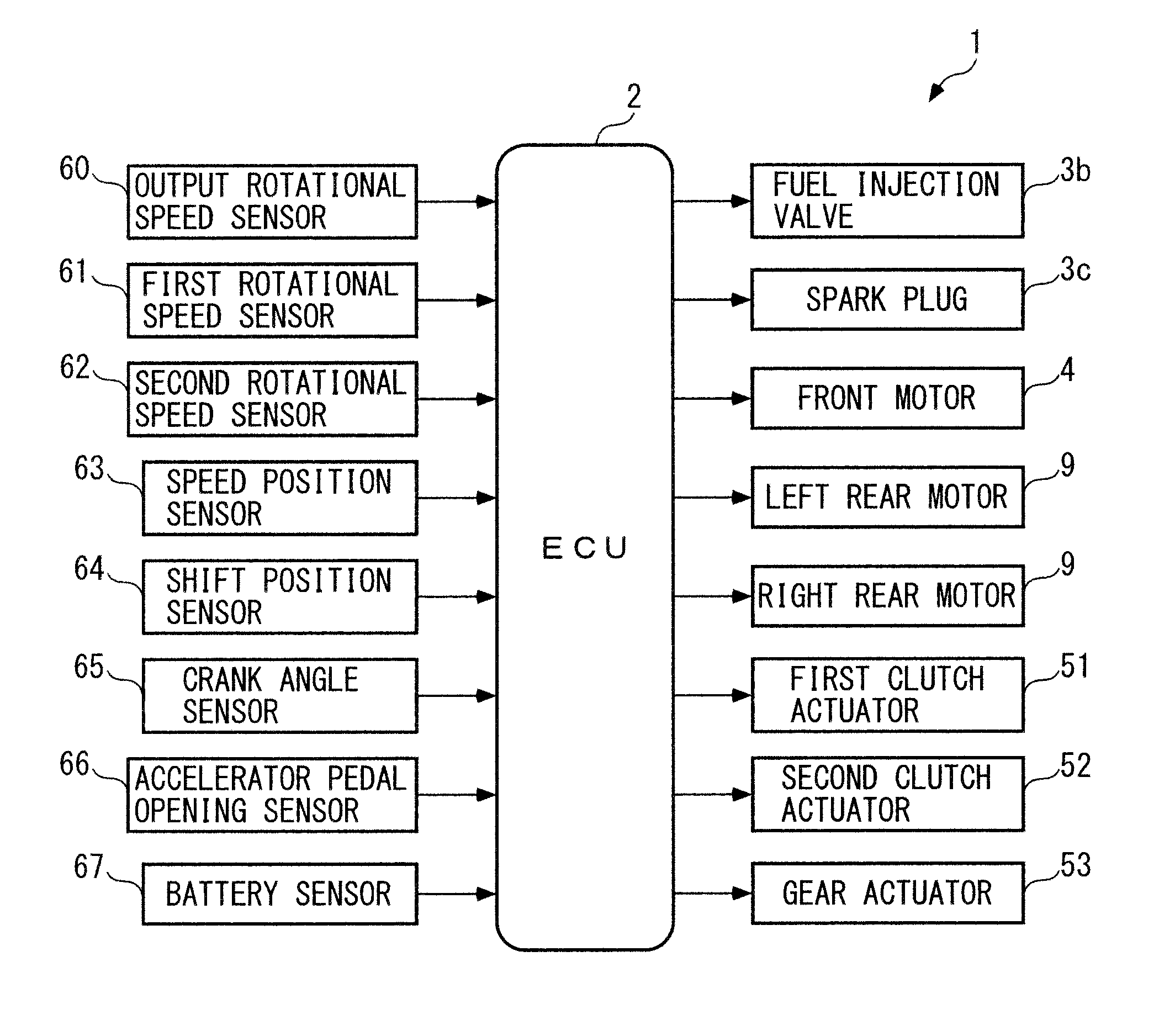
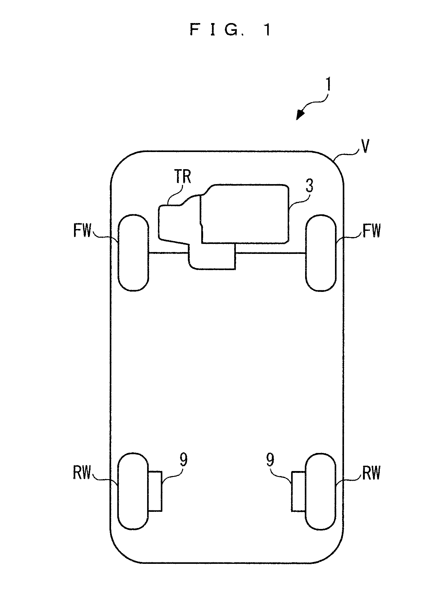
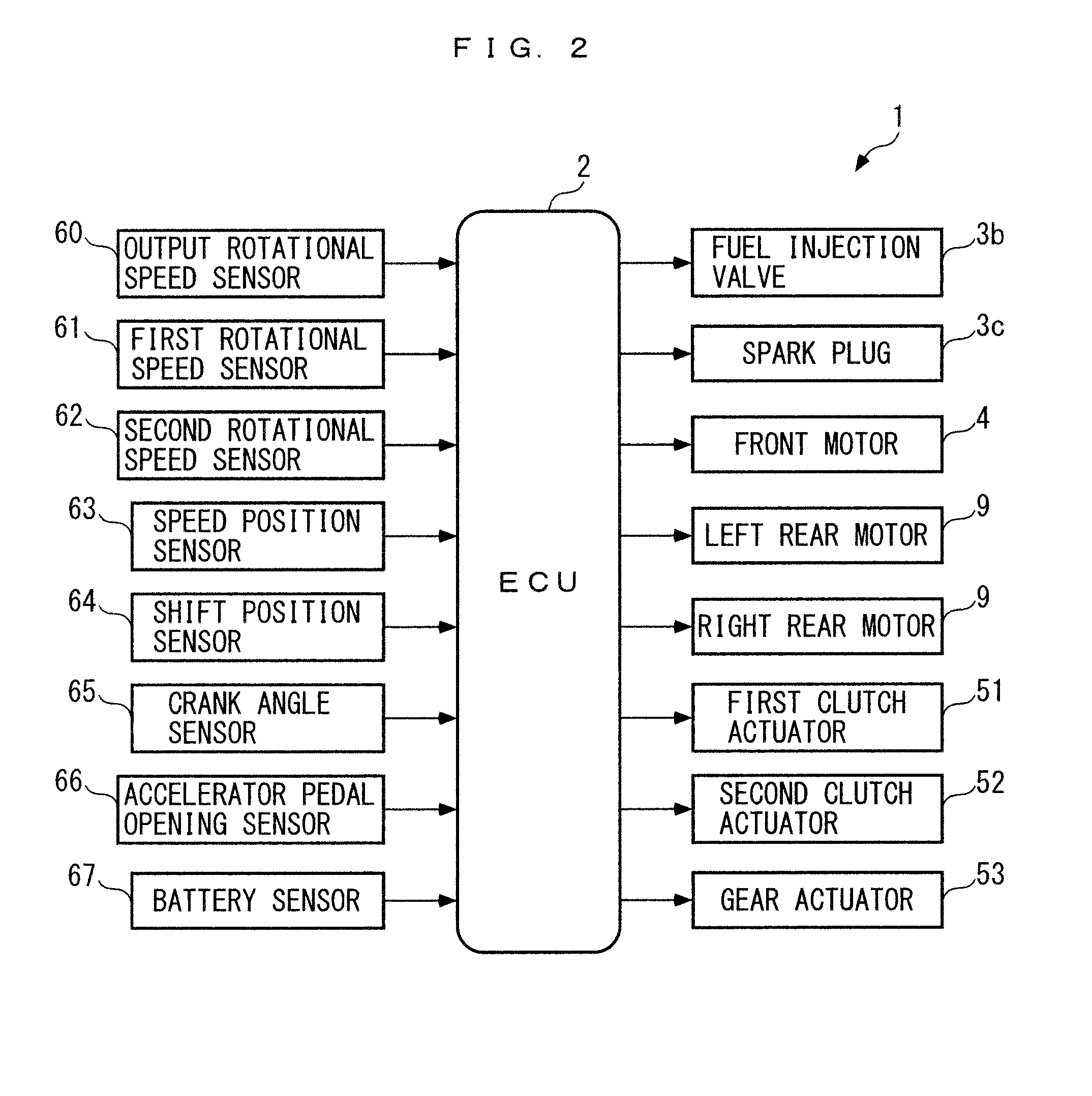
[0035]Hereafter, a drive device for a vehicle, according to an embodiment of the invention, will be described with reference to drawings. As shown in FIG. 1, the drive device, denoted by reference numeral 1, according to the present embodiment is applied to a vehicle V. The vehicle V is comprised of an internal combustion engine (hereafter referred to as the “engine”) 3 and a front motor 4 (see FIGS. 2 and 3) for driving left and right front wheels FW and FW, left and right rear motors 9 and 9 for driving left and right rear wheels RW and RW, and so forth.

[0036]In the vehicle V, the motive power of the engine 3 and / or the motive power of the front motor 4 are / is transmitted to the left and right front wheels FW and FW via an automatic transmission TR. Further, the left and right rear motors 9 and 9 are of an in-wheel motor type, and the left and right rear wheels RW and RW are directly driven by the left and right rear motors 9 and 9, respectively. That is, the vehicle V is configur...


PUM


Abstract

A drive device for a vehicle, which is capable of improving reliability of an in-gear operation for switching a speed position to an in-gear state while ensuring the degree of freedom in design of the drive device and realizing reduction of manufacturing costs thereof. When a transmission condition for transmitting motive power of the engine to front wheels via a first-speed forward position is satisfied, the ECU controls a first speed synchronization mechanism such that the first-speed forward position is switched to the in-gear state. At this time, if a condition of output shaft rotational speed≧predetermined detection lower limit is satisfied, the ECU controls the rotational speed of the front motor such that a ring gear speed is reduced, whereas if the condition is not satisfied, the ECU controls the same to a predetermined synchronization assist value for suppressing the rotational speed difference.

Description

BACKGROUND OF THE INVENTION[0001]1. Field of the Invention[0002]The present invention relates to a drive device for a vehicle, which is installed on the vehicle and transmits motive powers from an internal combustion engine and an electric motor to driven parts while changing speeds of the motive powers.[0003]2. Description of the Related Art[0004]Conventionally, as a drive device for a vehicle, one disclosed in Japanese Laid-Open Patent Publication (Kokai) No. 2008-302800 is known. This drive device for a vehicle is applied to a four-wheel vehicle, and transmits motive powers of the engine and the electric motor to drive wheels while changing the speeds of the motive powers. The drive device includes an input shaft connected to the engine, an output shaft connected to the drive wheels, two counter shafts connected to the input shaft via two clutches, and so forth. A gear group forming a first-speed to sixth-speed forward positions, a synchronization mechanism for connecting and dis...

Claims


Application Information

Patent Timeline
Patent Type & Authority Applications(United States)
IPC IPC(8): B60W20/00B60W10/10B60W10/08B60W10/02B60K6/54B60W10/06B60L50/16
CPCB60W20/10B60K6/54B60W20/30Y10S903/93B60W10/08B60W10/02B60W10/10B60W10/06B60K6/48B60K6/547B60K2006/4841Y02T10/62
Inventor YAMAMOTO, KAZUHISAISHII, SHINSUKE
Owner HONDA MOTOR CO LTD
Why Eureka
Try Eureka