
Sensor probe and related systems and methods

a technology of sensor probes and probes, applied in the field of sensor probes and sensor probe systems, can solve the problems of inability of thermocouples and rtds to easily conform, unnecessary cost, and impracticality in certain situations

Active Publication Date: 2015-06-04
MCCLELAND BARRY JOHN +1
View PDF19 Cites 132 Cited by
  • Summary
  • Abstract
  • Description
  • Claims
  • Application Information

AI Technical Summary

Benefits of technology

The patent describes a sensor probe system that includes one or more microelectromechanical systems (MEMS) sensors, a substrate, a communication bus, a digital storage module, and a cable. The sensor probe system is designed to communicate data to a remote monitoring unit for analysis and control purposes. The system has unique identifiers for each sensor and can store sensor data and control data in the digital storage module. The cable connects the sensor probe to the remote monitoring unit and provides power to the sensors. The system can operate at various environmental temperatures and is protected by a casing. The technical effects of this invention include improved accuracy and efficiency in sensing parameters, improved data communication with remote monitoring units, and increased flexibility and adaptability for sensor probe systems.

Problems solved by technology

Whilst thermocouples, thermistors and RTDs have been used for many years to monitor temperatures, and may well continue to play an important role in industry, there may be emerging applications that require a sensor probe with a suite of sensors and the thermocouples, thermistors and RTDs cannot easily conform.
For example, thermocouples, thermistors and RTDs are typically used for measuring temperature and provide a voltage as their output, making them impractical in certain situations.
Furthermore, providing a sensor probe and monitoring unit with each object may not be conducive to scalability and may also result in unnecessary cost.

Method used


Image

  • Sensor probe and related systems and methods
  • Sensor probe and related systems and methods
  • Sensor probe and related systems and methods

Examples


Embodiment Construction

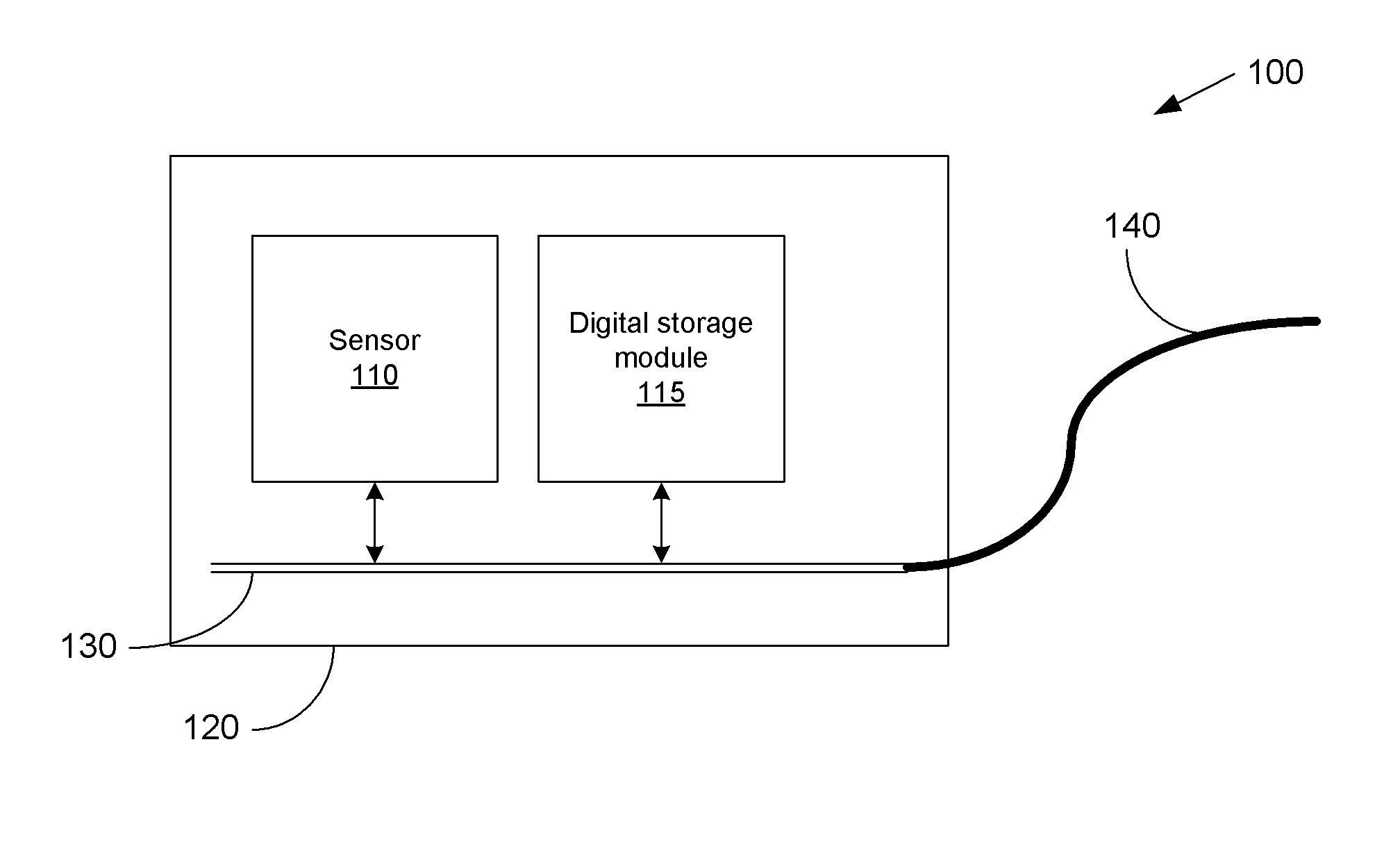
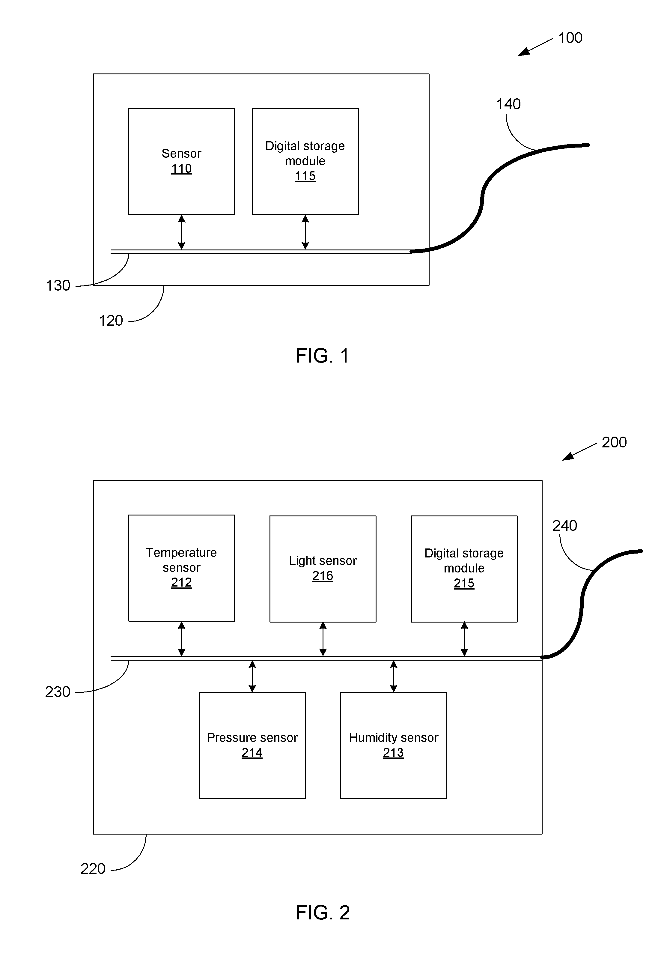
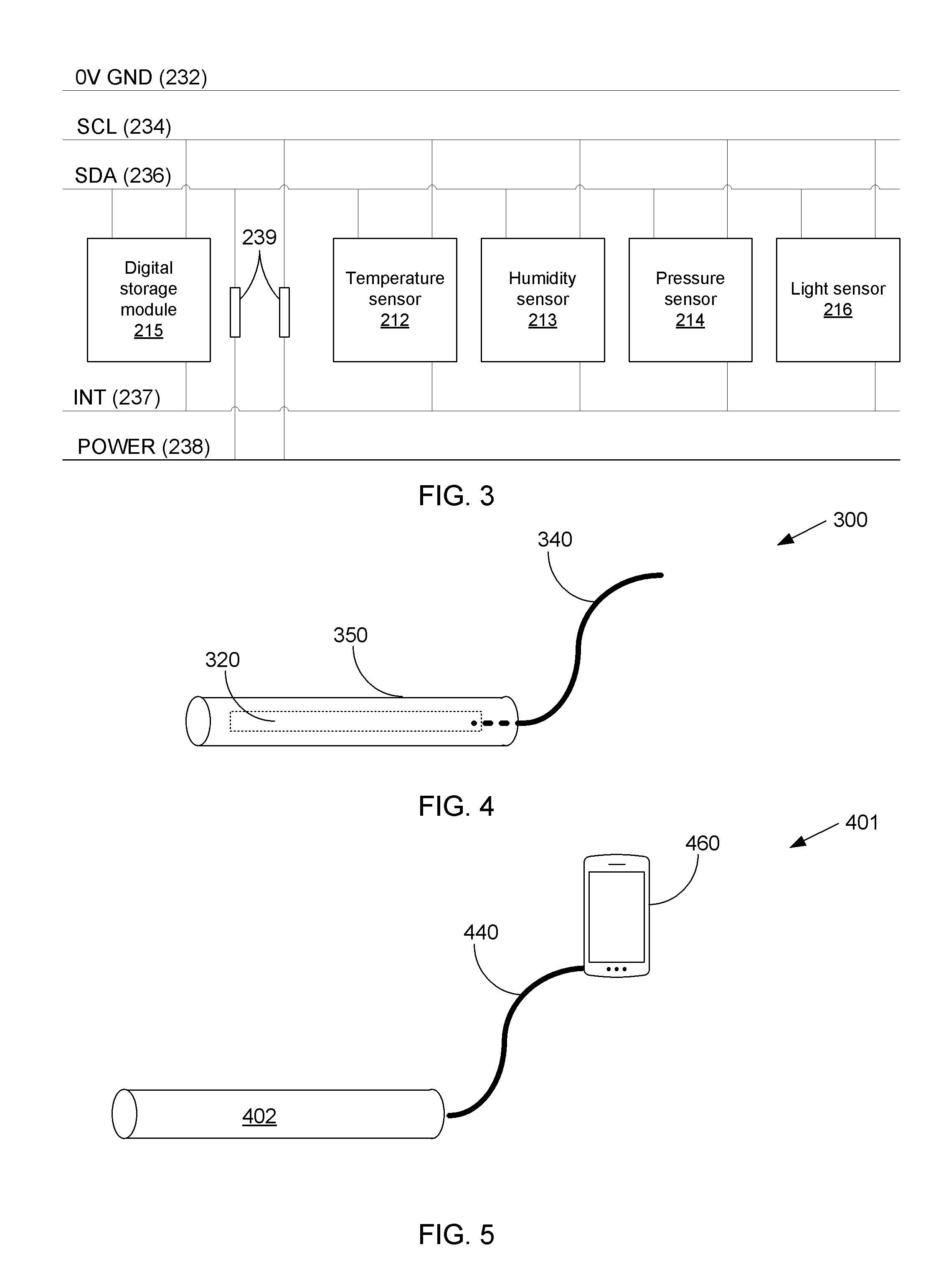
[0062]Embodiments of the invention are directed at a sensor probe and systems and methods relating thereto. FIG. 1 is a block diagram illustrating components of a sensor probe (100) according to an embodiment of the invention. The sensor probe has one or more microelectromechanical systems (MEMS) sensors (110) which are configured to sense parameters.

[0063]The terms MEMS sensors or microelectromechanical systems sensors, as used throughout this specification, are intended to have their broadest possible meaning and may include integrated circuit (IC) sensors and / or IC sensors having a small profile. A MEMS sensor may refer to a sensor IC that is disposed or incorporated onto a printed circuit board (PCB) with an interface to an external microcontroller (MCU), digital storage module such as non-volatile memory and power. The sensor probe according to embodiments of this invention, however, is not provided with an MCU or a power source. Instead, a remote device is provided which conta...


PUM


Abstract

The invention provides a sensor probe which has: one or more microelectromechanical systems (MEMS) sensors configured to sense one or more parameters and a communication bus in electrical communication therewith. The one or more sensors and communication bus are disposed on a substrate. The sensor probe includes a digital storage module in which a unique probe identifier is stored and which is in electrical communication with the communication bus. The probe includes, a cable, a first end of which is in electrical communication with the communication bus and a second end of which is in electrical communication with a remote monitoring unit. The cable is configured to provide electrical power received from the remote monitoring unit to the one or more sensors, via the communication bus, and to communicate data received from the one or more sensors, via the communication bus, to the remote monitoring unit.

Description

FIELD OF THE INVENTION[0001]This invention relates to a sensor probe and sensor probe systems, specifically to sensor probes and sensor probe systems used to monitor parameters associated with objects.BACKGROUND TO THE INVENTION[0002]Sensor probes may be used for measuring parameters such environmental conditions. The sensor probe may be inserted into an object or fixed in close proximity thereto and can monitor the environmental conditions of the object or to which it is exposed. The sensor probe may be permanently positioned or alternatively they may be temporarily positioned and used only to measure the environmental conditions of the object periodically. Temperature may be one of the most commonly measured parameters by sensor probes. Several types of sensor may be used for measuring temperature, such as thermocouples, thermistors and resistance temperature detectors (RTDs).[0003]Whilst thermocouples, thermistors and RTDs have been used for many years to monitor temperatures, an...

Claims


Application Information

Patent Timeline
Patent Type & Authority Applications(United States)
IPC IPC(8): B81B7/02
CPCB81B7/02G06F13/42G06F13/4282G06F13/4072H04Q9/00
Inventor MC CLELAND, BARRY JOHNVAN BELJON, EUGENE CHRISTIAAN
Owner MCCLELAND BARRY JOHN
Learn More