Air blower
a technology of air blower and air flow, which is applied in the direction of rotors, marine propulsion, vessel construction, etc., can solve the problems of air flow, inability to achieve sufficient noise reduction effect, and the blade cannot suitably deal with changes, so as to prevent the drop in air flow and effectively reduce the noise of the fan
- Summary
- Abstract
- Description
- Claims
- Application Information
AI Technical Summary
Benefits of technology
Problems solved by technology
Method used
Image

Examples
first embodiment
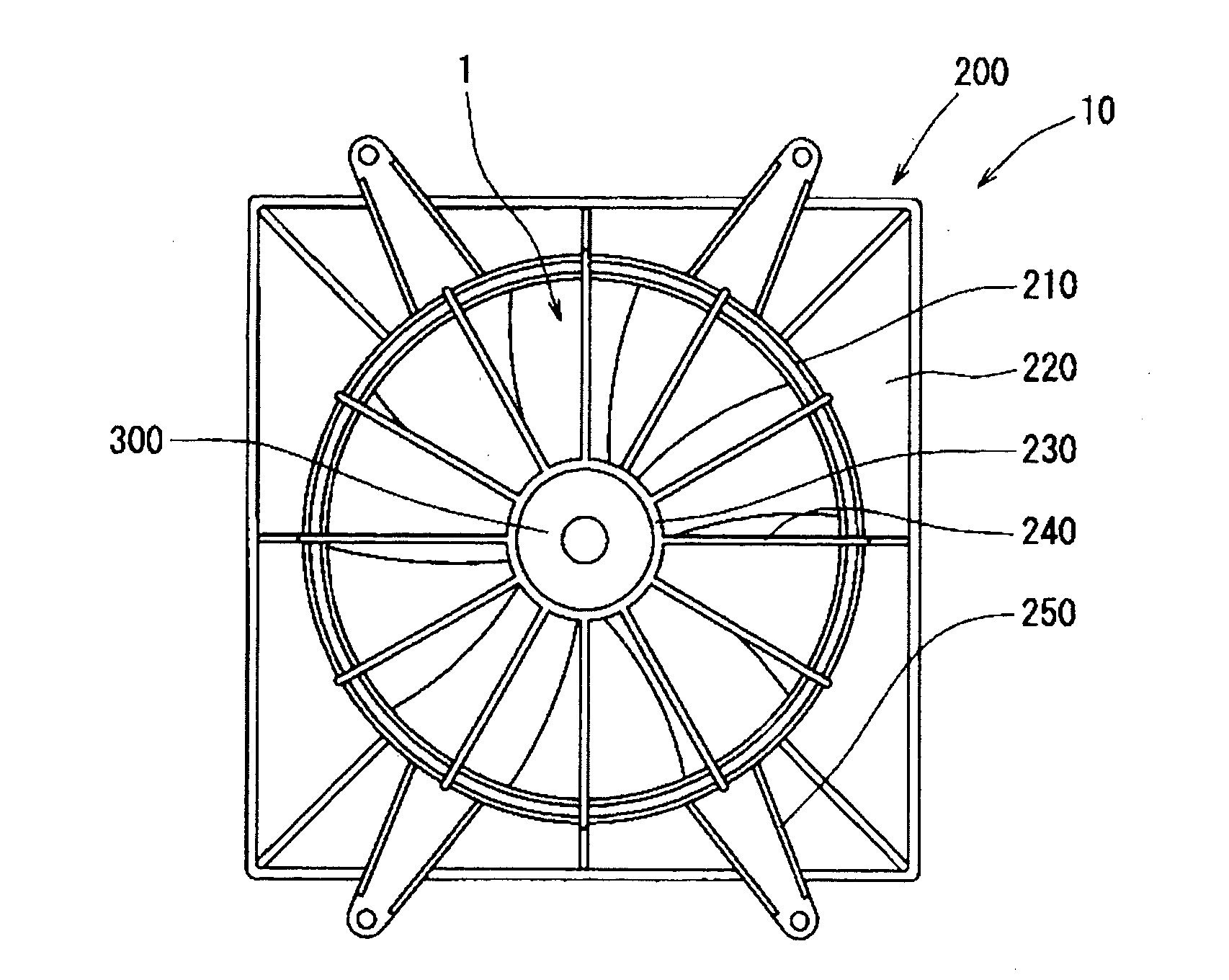
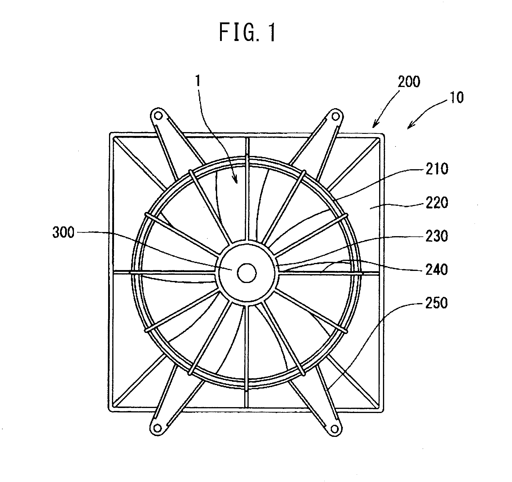
[0025]Referring to FIG. 1, a blower 10 is a so-called electric blower comprising a blower fan 1 which is placed in a shroud 200 and which is driven to rotate by a drive motor (electric motor) 300. The blower 10 is fastened to an engine side of an automobile radiator by mounts 250 which are provided near the four corners of the shroud 200 and blows air for cooling use to the core part of the radiator. The outside shape of the shroud 200 forms a rectangular shape corresponding to the core part of the radiator. At the approximate center, a ring-shaped shroud ring part 210 is formed so as to encircle the blower fan 1 by its outer circumference. This shroud ring part 210 is provided at the shroud 200 so as to be positioned at the outside of the ring 2 of the blower fan 1 in the radial direction. There may also be no ring 2 of the blower fan 1 in the present embodiment. The blower 10 and the later explained blades 3 of the present invention are not limited to use for an automobile radiato...
second and third embodiments
[0031]The second and third embodiments are embodiments corresponding to the case where the air near a blade surface of the blower flows in the circumferential direction of the blower fan. The second embodiment, as shown in FIG. 7, is characterized in that the further to the blade outside diameter side the blade is, the larger the sizes of the serrations are made. The serrations are directed toward the circumferential direction of the blower fan. According to this, the size of the serrations is increased at the portion with a large flow rate at the blade outer circumference side, and the whirled air flow which is formed at the serrations, becomes weaker at a portion further toward the blade inside circumference side and becomes stronger at a portion further toward the blade outer circumference side. Due to this, at the flow with a high flow rate where flow separation would easily occur, it is possible to form a downward flow toward the blade surface and reduce the flow separation to ...
fourth embodiment
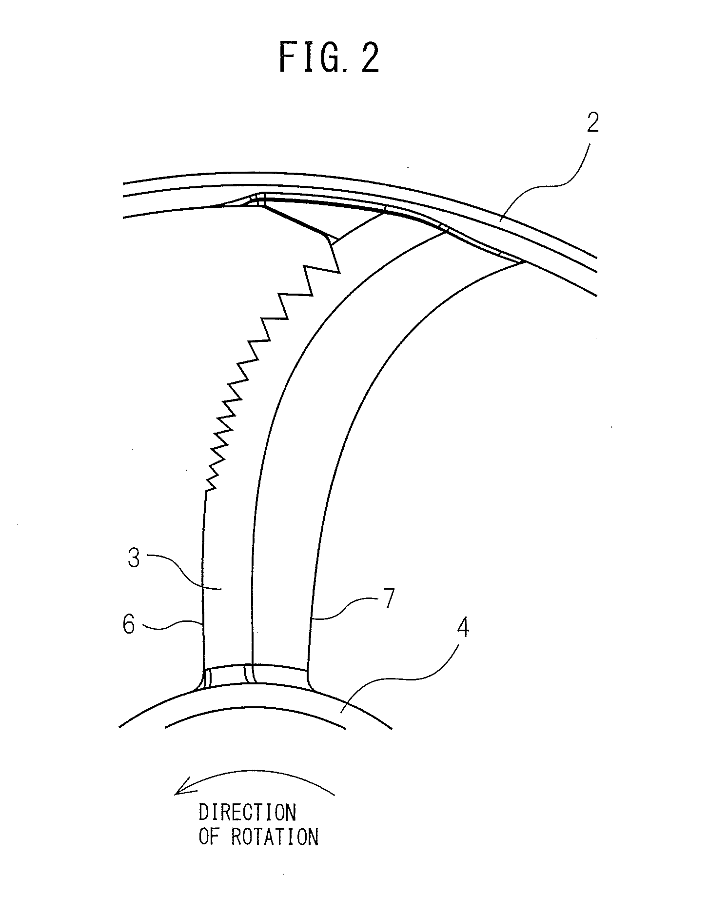
[0033]The fourth embodiment, as seen in FIG. 9, is characterized in that the blade trailing edge 7 is also provided with serrations and in that the blade leading edge 6 and blade trailing edge 7 are changed in serration shapes. When the blade trailing edge 7 is provided with serrations, since the flow at the high pressure blade positive pressure surface and the flow at the low pressure blade negative pressure surface are mixed near the blade trailing edge, the flows of the two surfaces gradually cross due to the serrations, so it is possible to suppress the disturbances in the flow of air of the blade trailing edge. The blade leading edge 6 and the blade trailing edge 7 may be suitably set with serration shapes. If the blade trailing edge 7 is made smaller in size of serrations compared with the blade leading edge 6, the serrations at the blade leading edge side, which are provided for suppressing flow separation, can be made larger so as to form a radiated flow. On the other hand, ...
PUM
 Abstract
Description
Claims
Application Information
 - R&D
- Intellectual Property
- Life Sciences
- Materials
- Tech Scout
- Unparalleled Data Quality
- Higher Quality Content
- 60% Fewer Hallucinations
Browse by: Latest US Patents, China's latest patents, Technical Efficacy Thesaurus, Application Domain, Technology Topic, Popular Technical Reports.
© 2025 PatSnap. All rights reserved.Legal|Privacy policy|Modern Slavery Act Transparency Statement|Sitemap|About US| Contact US: help@patsnap.com