Semiconductor module and driver device
- Summary
- Abstract
- Description
- Claims
- Application Information
AI Technical Summary
Benefits of technology
Problems solved by technology
Method used
Image

Examples
first embodiment
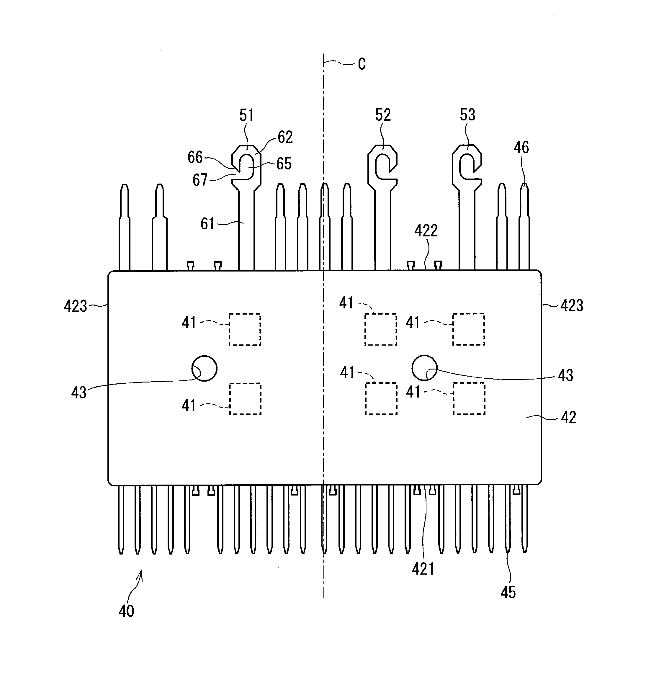
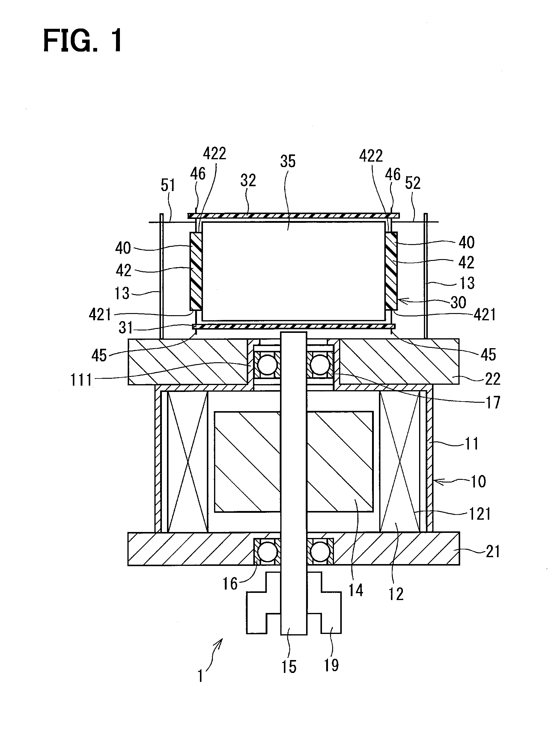
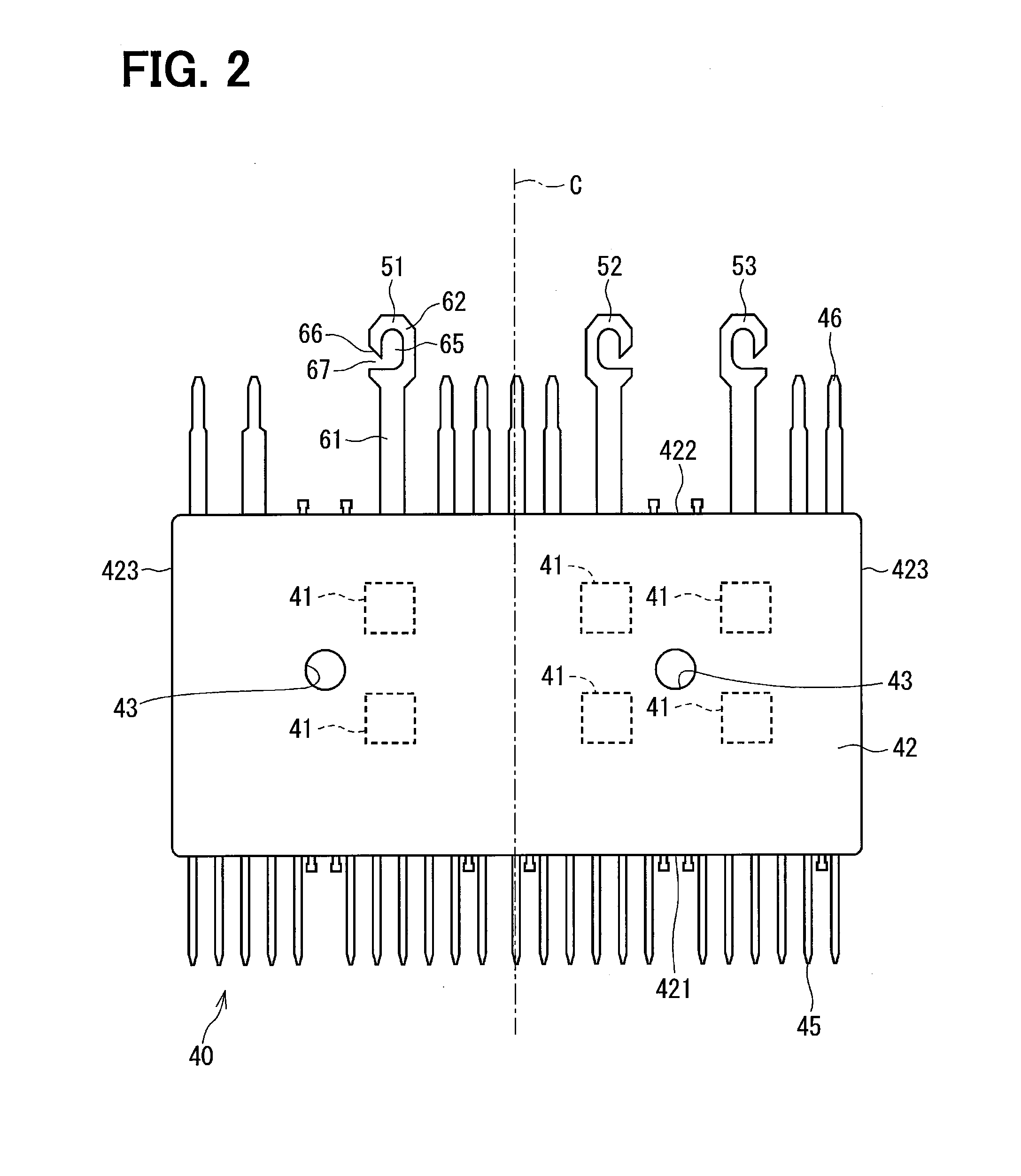
[0034]As shown in FIG. 1, a semiconductor module 40 in the first embodiment of the present disclosure is applied to a driver device 1. The driver device 1 is used in an electric power steering device of vehicles, for example. The driver device 1 has a motor 10 and a control unit 30. The driver device 1 of the present embodiment has a one-body construction in which the control unit 30 is disposed on one axial side of the motor 10 along a motor axis relative to the motor 10.
[0035]The motor 10 includes a motor case 11, a stator 12, a rotor 14, a shaft 15, a first frame 21, a second frame 22 and the like. The motor 10 in the present embodiment is a three-phase brush-less motor.
[0036]The motor case 11 is formed substantially in a cylinder shape, for example, by a soft magnetism material, such as iron.
[0037]The stator 12 has a winding wire 121 wound on a stator core that is fixedly disposed in an inside of the motor case 11. The winding wire 121 constitutes a three-phase circuit winding w...
second embodiment
[0085]The semiconductor module in the second embodiment of the present disclosure is shown in FIGS. 10 and 11. FIGS. 10 and 11 correspond to FIG. 9 of the first embodiment. A semiconductor module 48 of the present embodiment has three motor terminals 54, 55, and 56. The motor terminals 54, 55, and 56 are the same as that of the first embodiment, except that the length of the base portion 61 and the gap distance of the slot 67 differ from the one in the first embodiment. Since the length of the base portion 61 differs from the one in the first embodiment, the entire length of each of the motor terminals 54, 55, and 56 differs from the length of the motor terminal in the first embodiment. Further, in FIG. 11, one of the three terminals, i.e., the motor terminal 54 is reversed from the one in FIG. 10. Other than that, the configuration in FIG. 11 is the same as the configuration in FIG. 10.
[0086]Here, the motor terminal 54 is defined as having a length K1, the motor terminal 55 is defi...
third embodiment
[0092]The cutaway region shape in the third to fifth embodiments is different from the one in the first embodiment. Therefore, such a difference of the cutaway region shape is mainly described hereafter.
[0093]As shown in FIG. 12, a cutaway region 571 of a motor terminal 57 in the third embodiment of the present disclosure has a base side cutaway region face 572 serving as a first cutaway region face and a tip side cutaway region face 573 serving as a second cutaway region face, and forms a slot 575. The slot 575 is formed on one side in a width direction of the connection portion 62. The tip side cutaway region face 573 of the present embodiment is formed substantially in parallel with the base side cutaway region face 572. By forming the tip side the cutaway region face 573 and the base side cutaway region face 572 substantially in parallel with each other, the connectivity of the motor terminal 57 and the solder part 69 improves compared with a case in which the tip side cutaway r...
PUM
 Abstract
Description
Claims
Application Information
 - Generate Ideas
- Intellectual Property
- Life Sciences
- Materials
- Tech Scout
- Unparalleled Data Quality
- Higher Quality Content
- 60% Fewer Hallucinations
Browse by: Latest US Patents, China's latest patents, Technical Efficacy Thesaurus, Application Domain, Technology Topic, Popular Technical Reports.
© 2025 PatSnap. All rights reserved.Legal|Privacy policy|Modern Slavery Act Transparency Statement|Sitemap|About US| Contact US: help@patsnap.com