
Method and System for Optic Nerve Head Shape Quantification

a technology of optic nerve and quantification system, applied in the field of optic nerve head shape quantification, can solve the problems of inapplicability to pathologies with an increased onh, insufficient measurement of onh swelling, and limited existing methods

Inactive Publication Date: 2015-06-11
BRANDT ALEXANDER ULRICH
View PDF2 Cites 4 Cited by
  • Summary
  • Abstract
  • Description
  • Claims
  • Application Information

AI Technical Summary

Benefits of technology

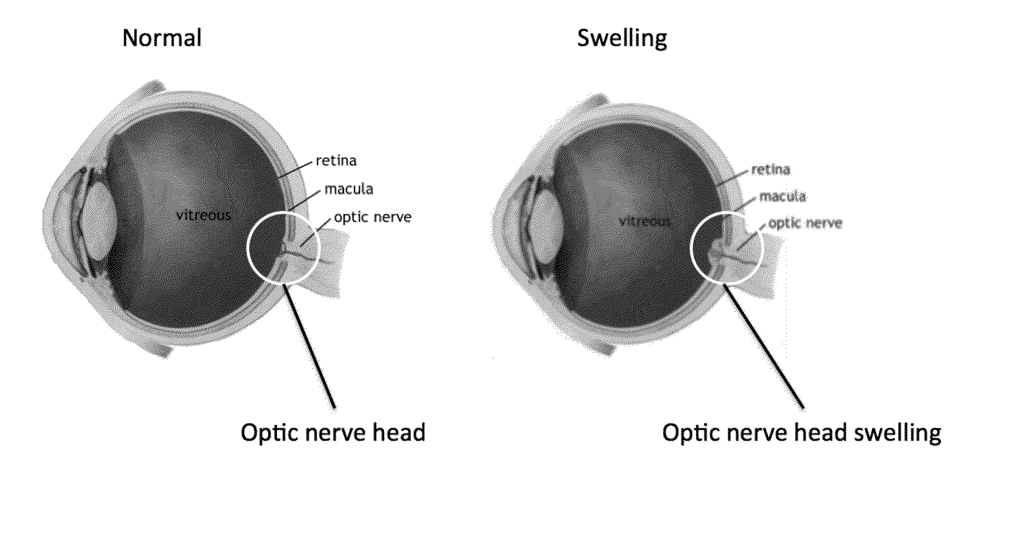
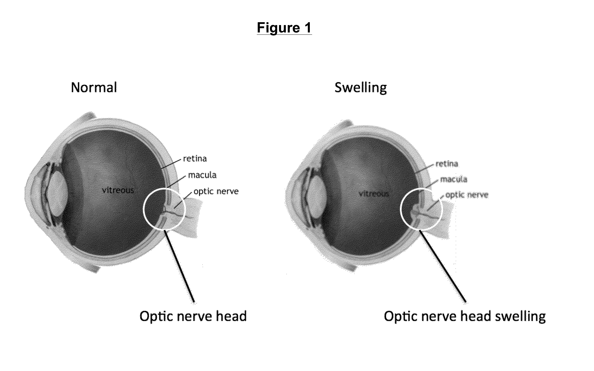
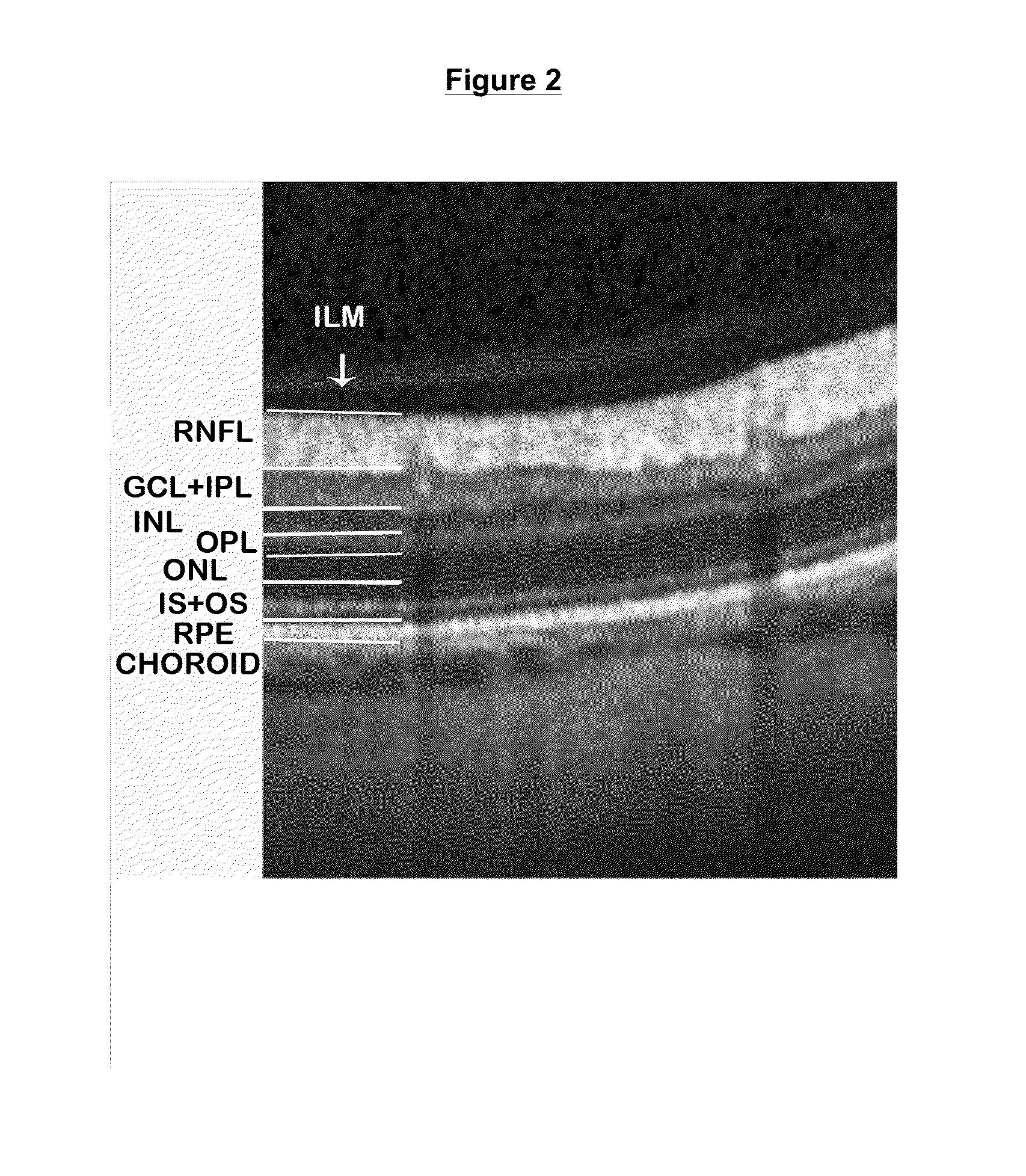
This patent describes a way to detect and reconstruct the outer layers of the retina using minimal information. This can be useful in conditions where the layers are not easily detectable in OCT. The method can provide information about optic nerve inflammation and intracranial pressure, and can help quantify the shape of the ONH (optic nerve head) which may be highly deformed in diseases such as multiple sclerosis, optic neuritis, and brain tumors.

Problems solved by technology

All existing methods are limited by their reliance on specific retinal layouts in order to work correctly.
These methods are inapplicable in pathologies with an increased ONH, because the swelling obscures the specialized segmentation routines.
Due to the inability of current methods to measure papilledema directly, previous clinical studies have used a commonly available method using the retinal nerve fiber layer thickness (RNFLT) in a peripapillary ring scan.
This only allows for inadequate measurement of ONH swelling, for example, lowering greatly sensitivity and specificity of the measurement.
With these limitations, ONH swelling quantification to measure e.g. optic nerve inflammation or intracranial pressure changes is not possible.

Method used


Image

  • Method and System for Optic Nerve Head Shape Quantification
  • Method and System for Optic Nerve Head Shape Quantification
  • Method and System for Optic Nerve Head Shape Quantification

Examples


examples

[0037]The method can be used to quantify ONH shape even in conditions when the ONH might be highly deformed, like, for example, in multiple sclerosis, neuromyelitis optica, optic neuritis, idiopathic intracranial hypertension, brain tumors, vascular disorders of the eye or optic nerve, normal pressure hydrocephalus or other diseases.

Example

Measurement of Swelling During an Acute Optic Neuritis or Vascular Event

[0038]In an exemplary embodiment of the present invention, swelling or flattening is quantified during an acute inflammation, e.g. an optic neuritis, both in single measurements (e.g. swollen / flattened ONH in comparison to a reference group (e.g. a reference database from healthy controls) and follow up measurements (e.g. ONH swelling or flattening over a period of time or in response to treatment in a single patient).

[0039]Further, swelling or flattening is quantified, for example, during an acute or chronic vascular event, e.g. an embolism of the central retinal artery, both...

example

Measurement of Real-Time ICP Changes

[0046]Further, by way of example, short-term changes in ICP are derived. For this, recorded B-scans are limited in number and ONH shape is derived from only few (as many as one) B-scan(s) to achieve a high time resolution. In this case, the ONH measurement can include less than the full ONH and be limited to a smaller area. B-scans are then recorded continuously over a time period and the changes in ONH shape (e.g. volume, area or height) are described over time.

[0047]FIG. 9 shows the workflow for this example: (1) OCT is taken from a single eye; (2) a defined region over the ONH is repeatedly measured over time; (3) ONH shape data is calculated using the described methods; (4) from these data over time real-time changes in ICP can be predicted; and (5) the validity of this may be supported by calibration data from cross-sectional studies comparing actual ICP with ONH shape data, or with specimen specific data from a single patient for longitudina...


PUM


Abstract

A fully automated optic nerve head description system based on optical coherence tomography that works with heavily deformed nerve heads and allows the generation of parameters describing swelling, including correlation with intracranial pressure both in detection and progression.

Description

[0001]This application claims the benefit of the filing date under 35 U.S.C. §119(e) of Provisional U.S. Patent Application Ser. No. 61 / 735,092, filed on Dec. 10, 2012, which is hereby incorporated by reference in its entirety.BACKGROUND OF THE INVENTION[0002]Optical coherence tomography (OCT) is a non-invasive imaging method, which creates in vivo cross-sectional patterns of the retina. In recent years, OCT has become a valuable tool for assessing retinal axonal damage in several neurological diseases such as optic neuritis, multiple sclerosis, neuromyelitis optica, spinocerebellar ataxia, and Parkinson's disease. Moreover, retinal changes measured with OCT are linked both with morphologic and metabolic changes in the brain, thus providing an easily accessible window into the brain in neurologic diseases.[0003]Modern spectral domain OCT allows for non-invasive, spatial imaging of retinal layers using manual or semi-automatic segmentation techniques. Some of these segmentation metho...

Claims


Application Information

Patent Timeline
IPC IPC(8): A61B3/10
CPCA61B3/102
Inventor BRANDT, ALEXANDER ULRICHKADAS, ELLA MARIAPAUL, FRIEDEMANNPOLTHIER, KONRAD
Owner BRANDT ALEXANDER ULRICH
Learn More