Liquid ejection apparatus

a liquid ejection and apparatus technology, applied in the direction of printing, other printing apparatus, etc., to achieve the effect of suppressing sedimentation, excellent dispersion stability of self-dispersion pigment, and suppressing unnecessary ink consumption

Active Publication Date: 2015-06-11
SEIKO EPSON CORP
View PDF2 Cites 19 Cited by
  • Summary
  • Abstract
  • Description
  • Claims
  • Application Information

AI Technical Summary

Benefits of technology

[0026]According to the aspect of the invention, since the liquid can suppress sedimentation due to aggregation of the pigment components and is an ink having excellent dispersion s

Problems solved by technology

However, in the ink jet printer, since it is not possible to determine whether the pigment component of the ink is settled, the flushing process is perf

Method used


Image

  • Liquid ejection apparatus
  • Liquid ejection apparatus
  • Liquid ejection apparatus

Examples


embodiment

A. Embodiment

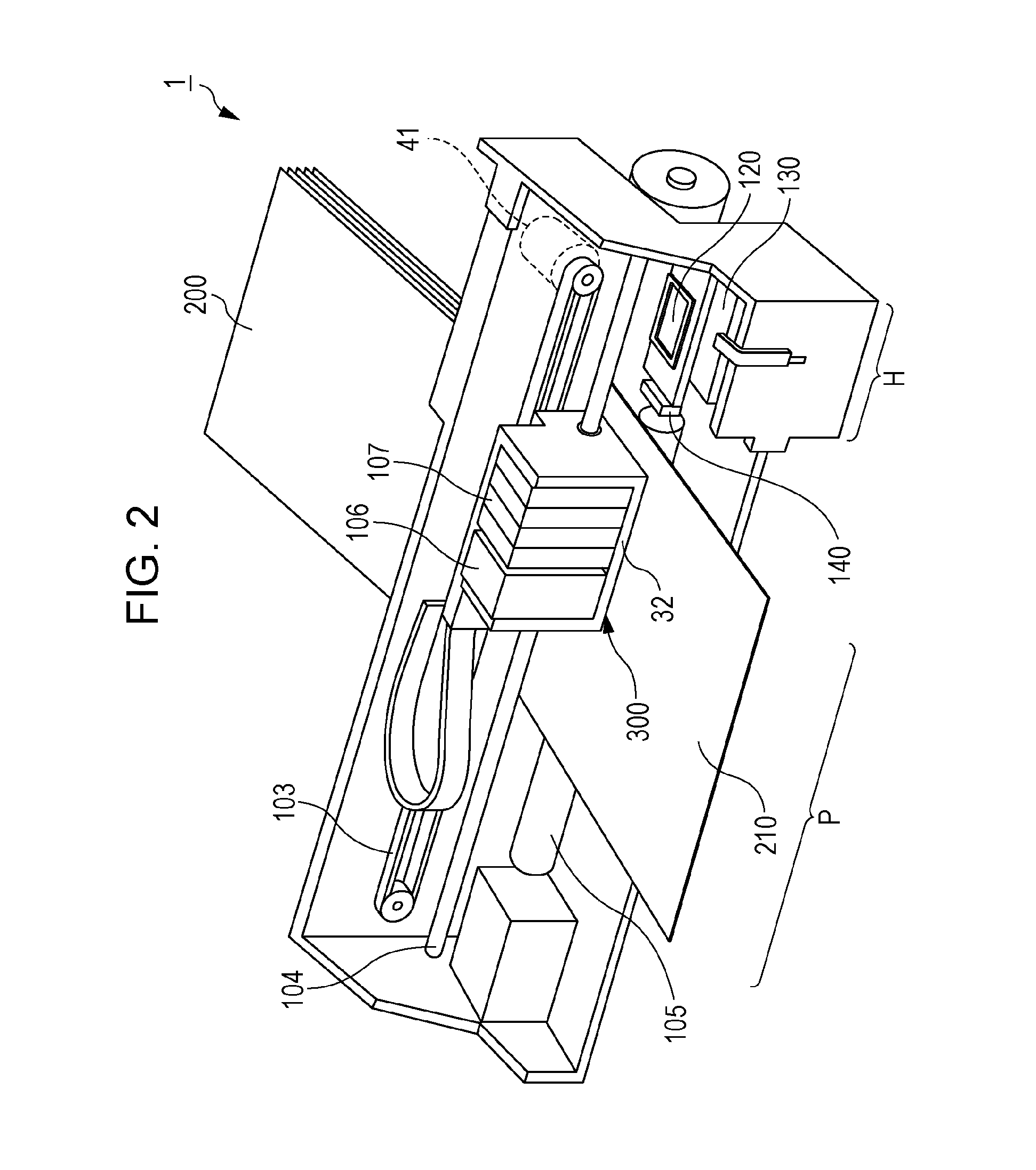
[0051]In the present embodiment, an ink jet printer that ejects an ink (an example of a “liquid”) and forms an image in a recorded medium (for example, paper for recording) will be described as an example of a liquid ejection apparatus.

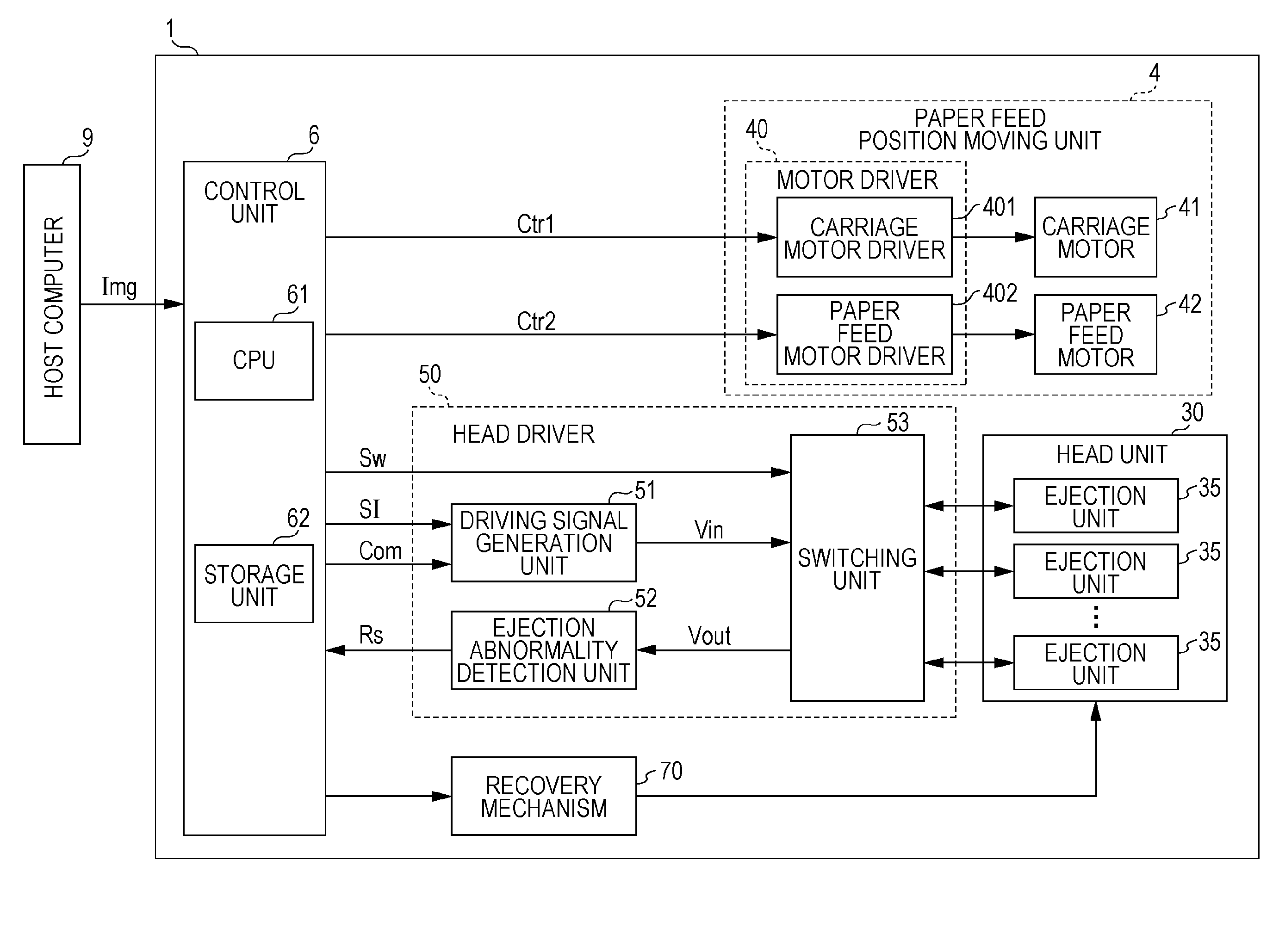
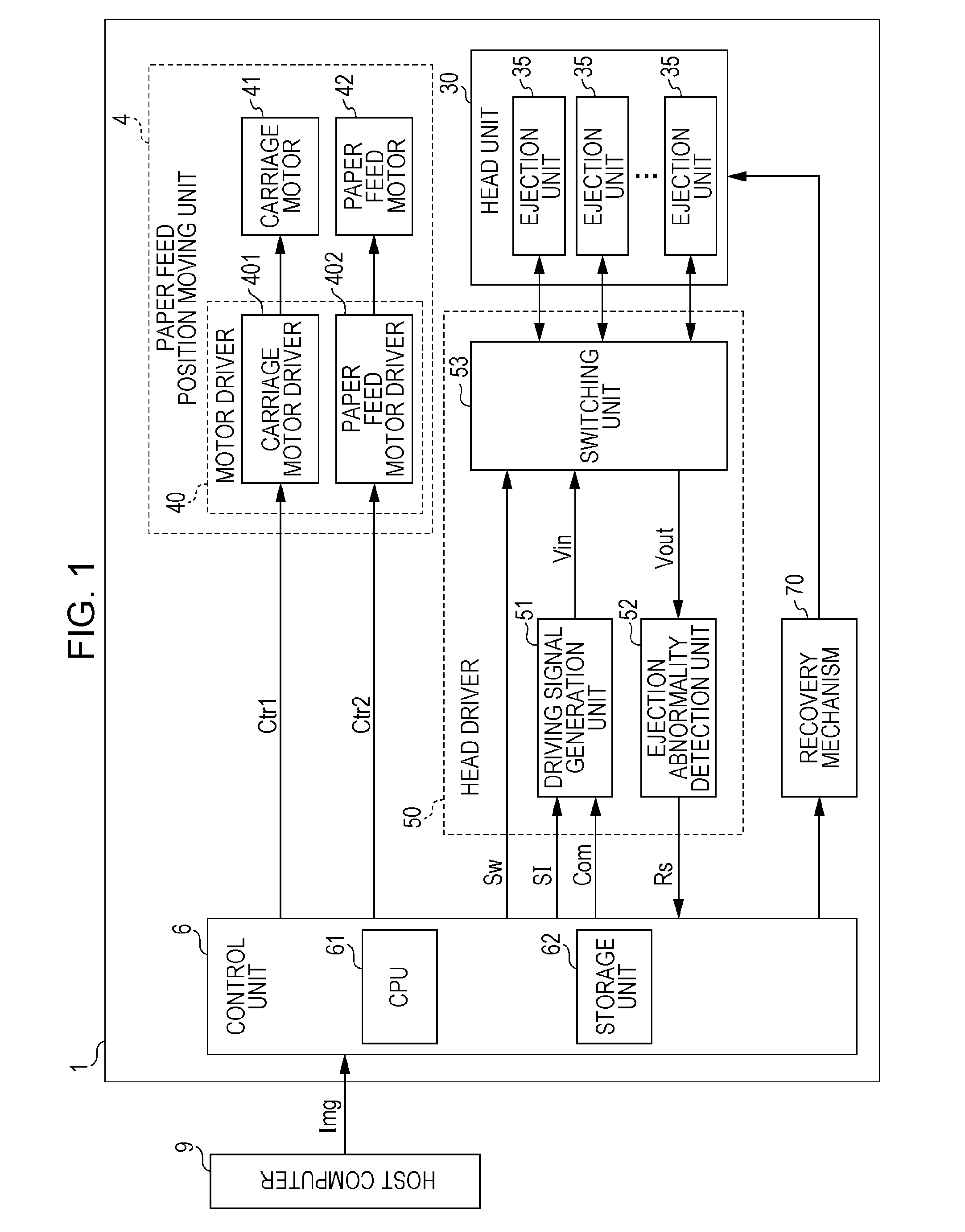
[0052]FIG. 1 is a functional block diagram illustrating a configuration of an ink jet printer 1 according to the present embodiment. As illustrated in the figure, the ink jet printer 1 includes a head unit 30 including M ejection units 35 (M is a natural number of 2 or more) which can eject an ink filled therein, a head driver 50 driving the head unit 30, a paper feed position moving unit 4 for moving a relative position of the head unit 30 with respect to a recorded medium, and a recovery unit 70 that performs a recovery process for recovering a normal ejecting function of the ejection unit 35 in a case where “a state of an ink which may cause an ejection abnormality (hereinafter, simply referred to as “ejection abnormality”)” is detecte...

first modified example

[0209]The description overlapping with the above-described embodiment will be omitted and only differences will be described. The differences are the determination process performed by the determination unit 56 of the ink jet printer 1. That is, the process of the flowchart described with reference to FIG. 18 is merely an example and the processes in all steps are not necessarily performed and the process order of each step is not necessary to follow. Hereinafter, details will be described.

[0210]When the process of determining the causes on the ejection abnormality is performed, the determination unit 56 can perform the determination processes in steps which are executable in an arbitrary timinig after information (the validity flag Flag, the detection signal NTc (that is, the cycle T of the residual vibration), or the amplitude A) that makes the determination processes in each step possible is input.

[0211]Specifically, the determination unit 56 may perform the determination process...

second modified example

[0212]The driving signal Vin for inspection in the above-described embodiment adopts the first potential V1, the second potential V2, and the third potential V3, but the invention is not limited thereto, and the driving signal Vin may be a signal waveform including four or more kinds of potential.

[0213]For example, as illustrated in FIG. 20, a fourth period T4 that maintains a fourth potential V4 is provided in a period between the end time t1e of the first period T1 and the start time t2s of the second period T2, the driving signal may be moved from the first potential V1 to the fourth potential V4 from the time t1e to the time t4s, and the driving signal may be moved from the fourth potential V4 to the second potential V2 from the time t4e to the time t2s.

[0214]Here, a potential difference ΔV42 between the fourth potential V4 and the second potential V2 is larger than a potential difference ΔV12 between the first potential V1 and the second potential V2. Accordingly, the driving s...


PUM


Abstract

An ink jet printer includes an ejection unit including a nozzle which ejects a liquid containing a pigment; a cavity which communicates with the nozzle; and a piezoelectric element which is provided in the cavity, and a driving signal generation unit which generates a driving signal allowing the piezoelectric element to be displaced such that the cavity expands or is contracted. The ink jet printer includes a detection unit that detects a cycle of a residual vibration waveform of the piezoelectric element which is generated by the driving signal being applied to the piezoelectric element and indicates a value according to change of the pressure inside of the cavity and a determination unit that determines the pigment is settled based on the cycle of the residual vibration waveform detected by the detection unit.

Description

BACKGROUND[0001]1. Technical Field[0002]The present invention relates to inspection on an ejection state of a liquid ejection apparatus.[0003]2. Related Art[0004]An ink jet type printer (hereinafter, referred to as an “ink jet printer”) performs printing by ejecting an ink in a cavity. The ink is thickened when dried. When the ink in the cavity is thickened, this might cause ejection failure. In addition, when bubbles are included in the ink in the cavity or paper dust is adhered to a nozzle which ejects the ink, this might cause ejection failure as well. Accordingly, it is preferable that the ejection state of the ink be inspected.[0005]JP-A-2004-299341 (FIG. 26) discloses a method of vibrating an ink in the cavity using a piezoelectric element and determining the ejection state by sensing behavior of the ink with respect to the residual vibration.[0006]However, in the ink used for the liquid ejection apparatus, an ink of a pigment component contained in the ink with a high sedimen...

Claims


Application Information

Patent Timeline
IPC IPC(8): B41J2/045
CPCB41J2/04581B41J2/04588B41J2/0451B41J2/04541B41J2/04593B41J2002/14354B41J2/04596
Inventor SUZUKI, TOSHIYUKISHINKAWA, OSAMU
Owner SEIKO EPSON CORP
Why Eureka
Try Eureka