
Fuel injection valve for internal combustion engines

a technology for internal combustion engines and fuel injection valves, which is applied in the direction of fluid pressure injection control, fuel injection apparatus, discharge feed systems, etc., can solve the problems of cumbersome and expensive control by way of a 3/2 directional valve, so-called discharge quantity is basically unavoidable, and reduces the efficiency of the injection system

Active Publication Date: 2015-06-11
ROBERT BOSCH GMBH
View PDF11 Cites 7 Cited by
  • Summary
  • Abstract
  • Description
  • Claims
  • Application Information

AI Technical Summary

Benefits of technology

The invention is a fuel injection valve that reduces fuel discharge quantity without affecting control dynamics. It includes a control piston that separates the control chamber into two parts. The control piston is moved by hydraulic forces alone and is positioned to control the fuel injection system. The closure of the inflow throttle during the opening phase of the fuel injection valve prevents fuel from flowing into the control chamber, reducing fuel consumption in the motor vehicle equipped with the fuel injection system. In addition, the control piston is subjected to an opening force to ensure a distinct function. The invention is easy and inexpensive to realize and permits a wide range of variability in arrangement of the control piston and valve piece.

Problems solved by technology

This so-called discharge quantity is basically unavoidable owing to the construction principle.
Said fuel must be compressed by the high-pressure pump in addition to the fuel intended for injection, which reduces the efficiency of the injection system.
The control by way of a 3 / 2 directional valve is however cumbersome and expensive.
Furthermore, the build-up and dissipation of pressure in the control chamber is relatively slow in the case of this embodiment.

Method used


Image

  • Fuel injection valve for internal combustion engines
  • Fuel injection valve for internal combustion engines
  • Fuel injection valve for internal combustion engines

Examples


Embodiment Construction

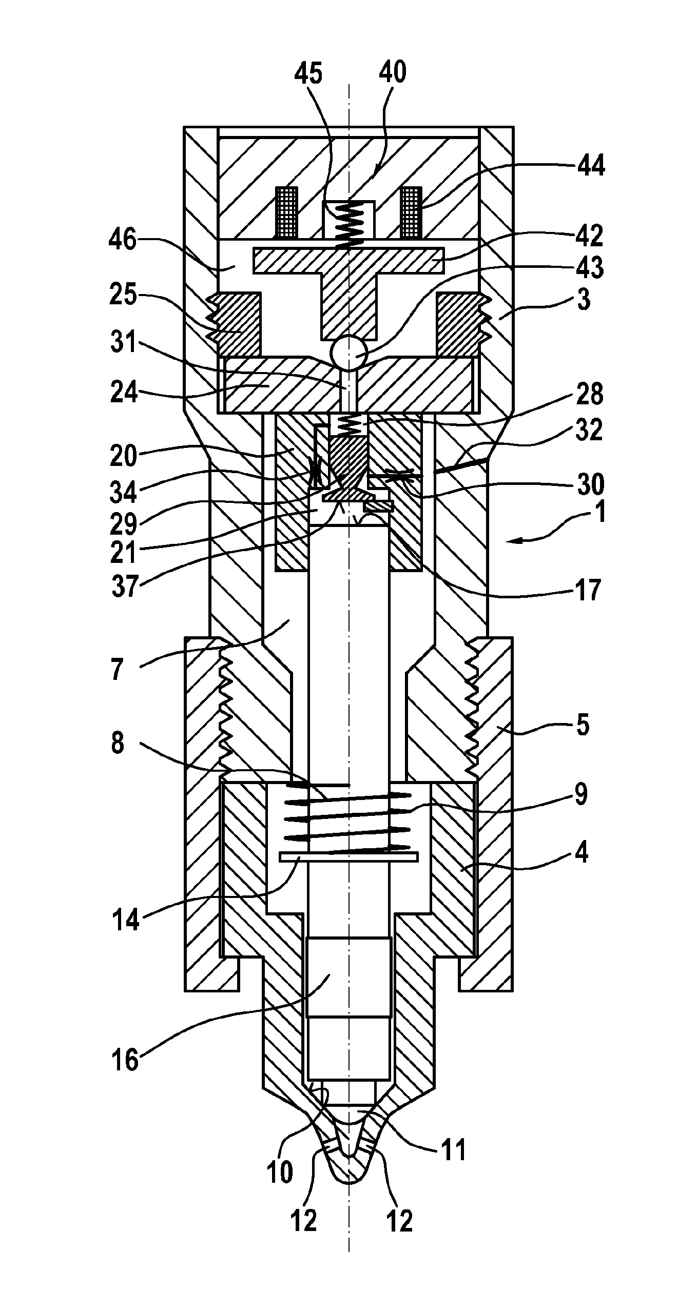
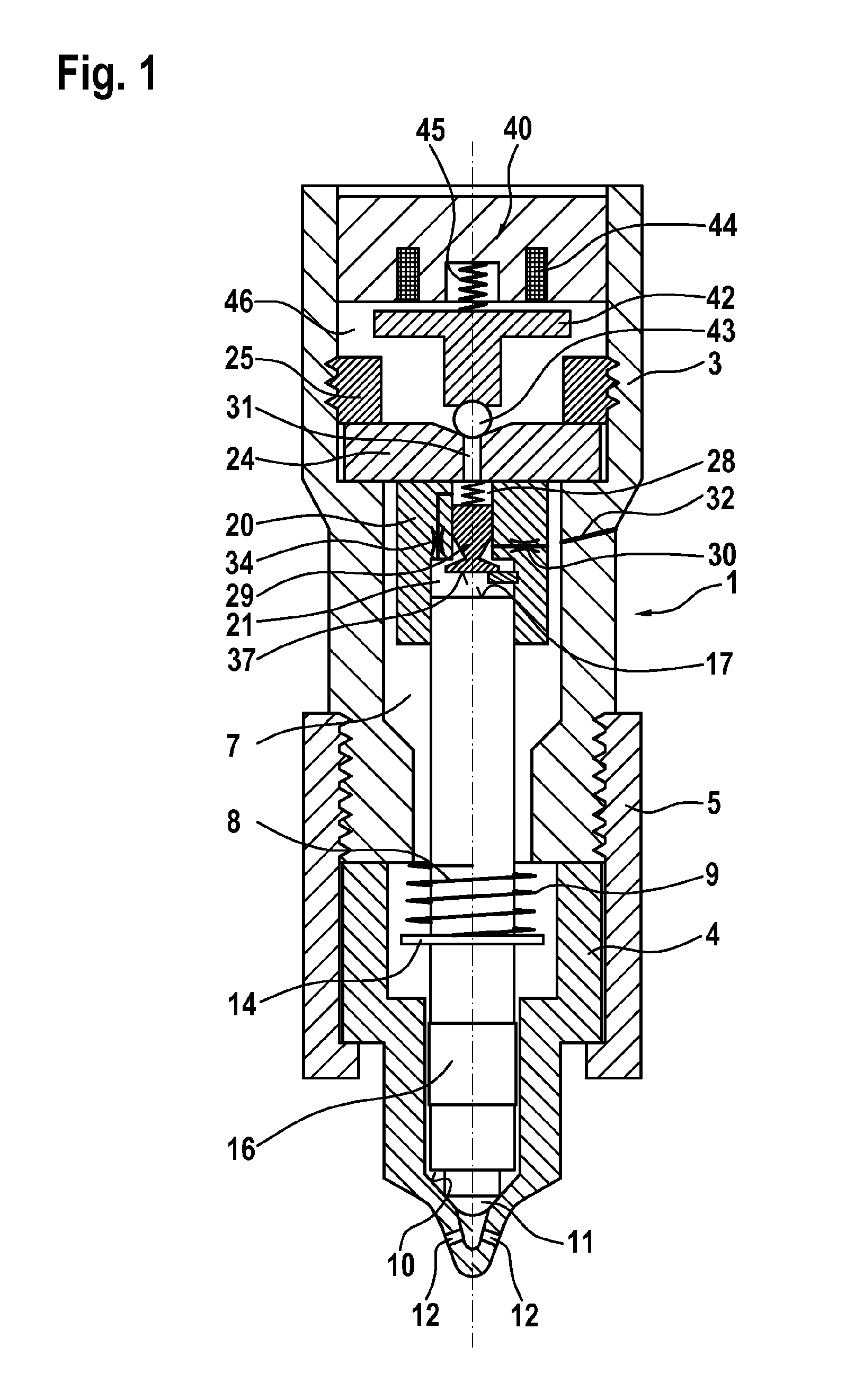
[0017]FIG. 1 schematically illustrates a fuel injection valve according to the invention in longitudinal section. The fuel injection valve has a housing 1 which has a holding body 3 and a nozzle body 4 which are braced against one another by means of a clamping nut 5. In the holding body 3 and in the nozzle body 4 there is formed a pressure chamber 7 which can be filled with fuel at high pressure via a high-pressure port 32. In the pressure chamber 7 there is arranged, in longitudinally displaceable fashion, a nozzle needle 8 which, on its end which faces toward an internal combustion engine in an installed position, has a valve sealing surface 11 by means of which the nozzle needle 8 interacts with a nozzle seat 10 and thereby controls the connection of multiple injection openings 12, which are formed in the nozzle body 4, to the pressure chamber 7. In this case, the nozzle needle 8 is guided, in the region of the nozzle body 4, in a guide section 16, wherein the fuel flow through ...


PUM


Abstract

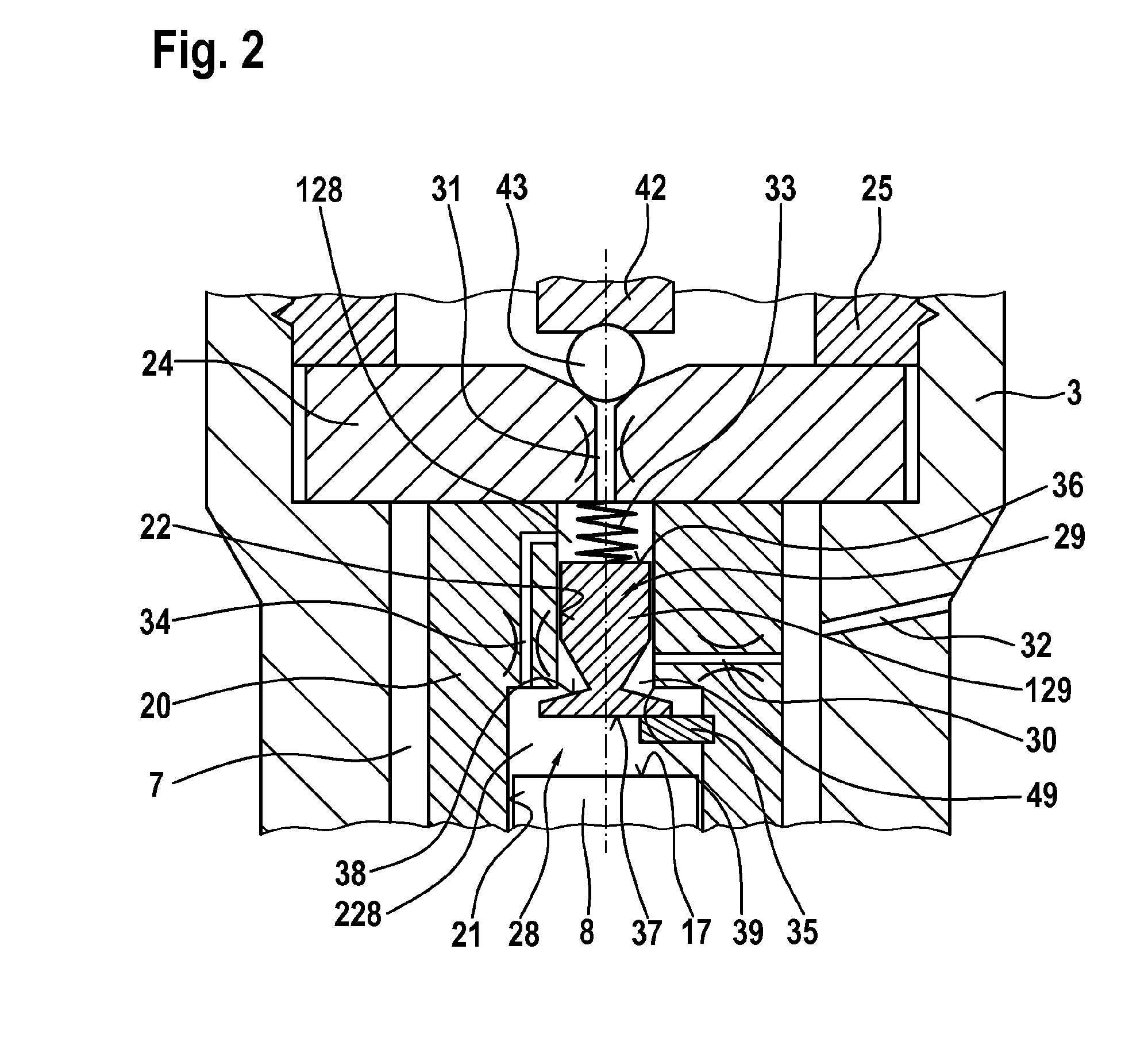
The invention relates to a fuel injection valve comprising a housing (1) in which pressure is applied to a nozzle needle (8), in a control chamber (28), at least indirectly with a closing force in the direction of a valve seat (10). The pressure in the control chamber (28) can be adjusted using a control valve (40) as said control chamber (28) is able to be connected to a low pressure chamber (46) via an outlet restrictor (31) and be filled with fuel at high pressure via an inlet restrictor (30). A longitudinally-displaceable control piston (29) is arranged in the control chamber (28) and divides said chamber (28) into a first control sub-chamber and a second control sub-chamber (228), the first control sub-chamber (128) being able to be connected to the low pressure chamber (46) by means of said outlet restrictor (31). A sealing surface (38) is formed on the control piston (29) and interacts with a sealing seat (39) in the control chamber (28) such that the inlet restrictor (30) is hydraulically disconnected from the second control sub-chamber (228) when the sealing surface (38) comes to rest against the sealing seat (39). Said first control sub-chamber (128) and second control sub-chamber (228) are constantly hydraulically interconnected by means of a restrictor connection (34).

Description

BACKGROUND OF THE INVENTION[0001]The invention relates to a fuel injection valve for internal combustion engines, such as is preferably used for the injection of fuel into a combustion chamber of an auto-ignition internal combustion engine.[0002]Injection systems for the injection of fuel into combustion chambers at high pressure are known from the prior art. Here, fuel is compressed by a high-pressure pump and is temporarily stored in a high-pressure accumulator, a so-called rail. Said high-pressure accumulator provides a feed to one or more fuel injection valves which inject the required fuel into the respective combustion chamber. It is an aim here for exactly the required fuel quantity to be introduced into the combustion chamber as finely atomized and spatially uniform a manner as possible. DE 100 24 702 A1, for example, presents an injection system of said type together with injection valve.[0003]To control the injection, the known fuel injection valves have a nozzle needle wh...

Claims


Application Information

Patent Timeline
IPC IPC(8): F02M47/02F02M63/00
CPCF02M47/02F02M63/0043F02M63/0075F02M47/025F02M61/20F02M63/0029F02M63/0042F02M2547/003F02M47/027
Inventor MAGEL, HANS-CHRISTOPHGRUENBERGER, ANDREAS
Owner ROBERT BOSCH GMBH
Learn More