
Internal Combustion Engine Having An Elastic Connector And Method Of Producing Same

a technology of elastic connectors and internal combustion engines, which is applied in the direction of combustion engines, machines/engines, manufacturing tools, etc., can solve the problems of internal combustion engine stalling, disruption of running conditions, and inability to arbitrarily compensate for greater rigidity by different materials or thinner wall thicknesses

Active Publication Date: 2009-07-30
ANDREAS STIHL AG & CO KG
View PDF11 Cites 15 Cited by
  • Summary
  • Abstract
  • Description
  • Claims
  • Application Information

AI Technical Summary

Benefits of technology

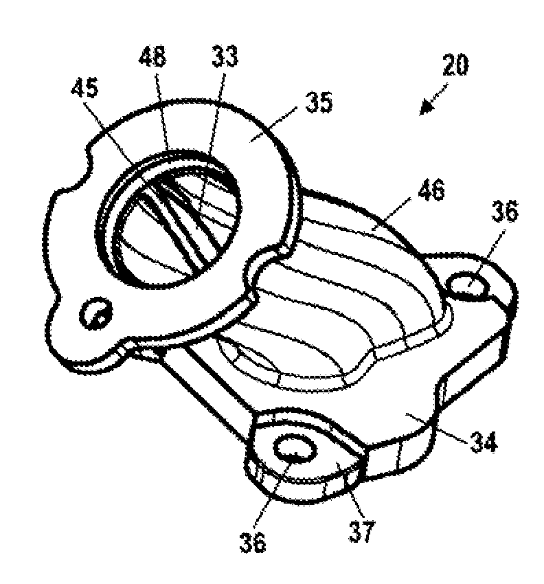
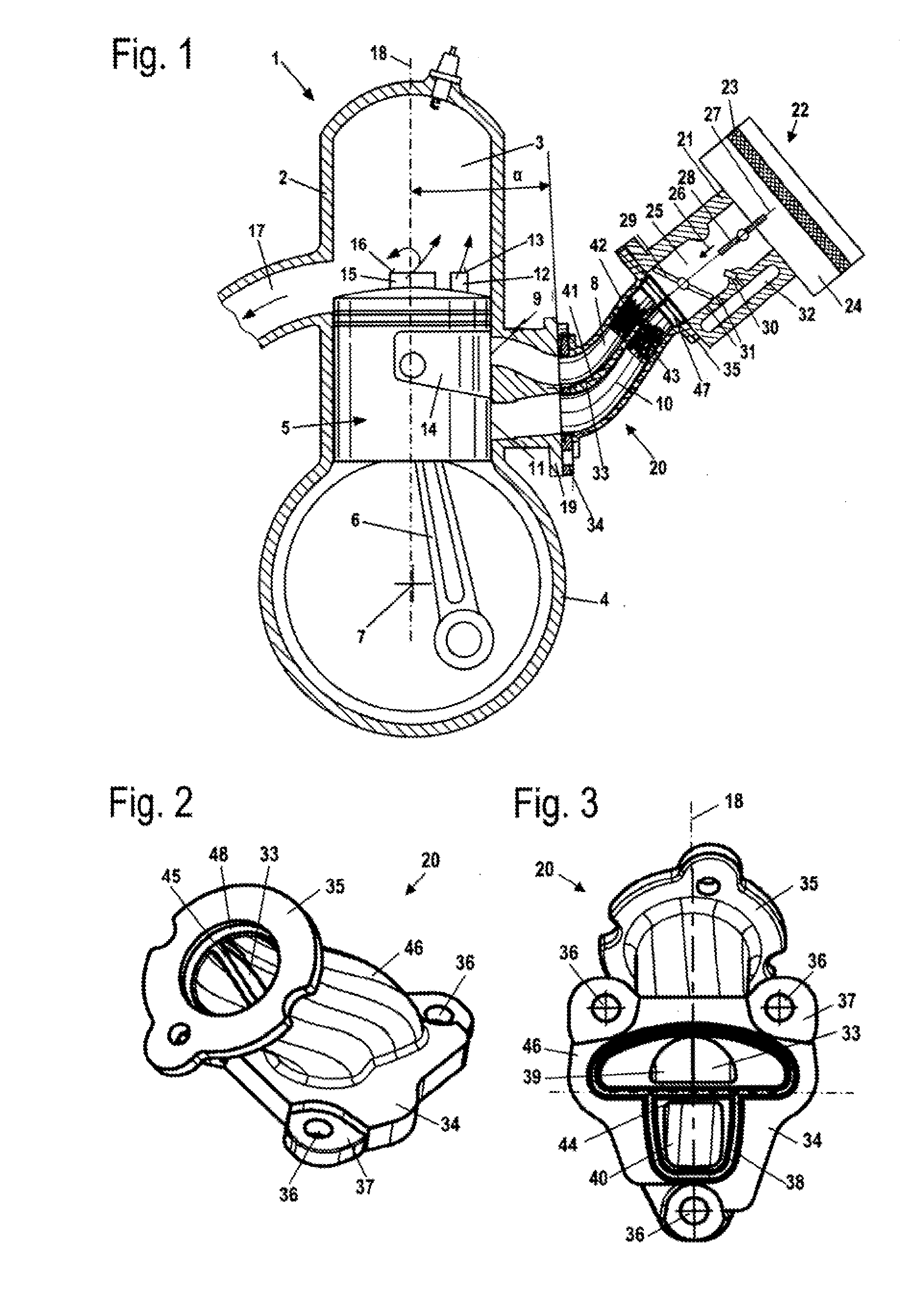
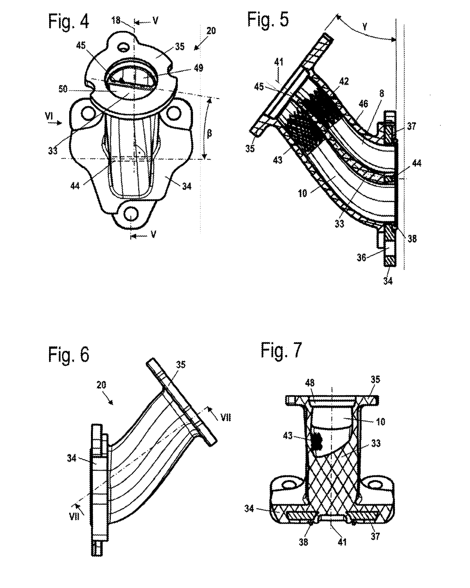
[0035]To achieve a straightforward construction of the internal combustion engine, a first channel for fuel / air mixture and a second channel for combustion air are formed in the elastic connector. The two channels are separated from one another by a partition. The partition, which extends in the longitudinal direction of the connector, increases the stability of the connector in the longitudinal direction, thus making the connector less elastic. However, this greater rigidity cannot arbitrarily be compensated for by a different material or thinner wall thicknesses, since thinner wall thicknesses or the selection of a softer material for the elastic connector could, under certain operating conditions, promote collapse of the channel walls of the connector. In such a case, the connector bends, so that the channels can temporarily be at least partially closed off. This can lead to disruptions in running conditions and even stalling of the internal combustion engine. In order to nonetheless achieve an adequately high elasticity of the connector, the partition is twisted about its longitudinal central axis between the first and the second connection ends. The twisting of the partition about its longitudinal central axis reduces the rigidity of the connector in its longitudinal direction. In this way, an adequate thickness and rigidity of the partition can be ensured, thus ensuring the function of the connector.
[0045]At least one of the channels is provided with a structured inner surface, which includes pyramid-shaped raised portions. To ensure that the pyramid-shaped raised portions can be removed from a mold, the raised portions, especially the side surfaces of the raised portions that are disposed in the longitudinal direction of the channel, are oriented approximately parallel to the direction of pulling. As a result, a tearing-off of the raised portions during the movement of the cores relative to one another is avoided. The surfaces of the pyramid-shaped raised portions that are oriented parallel to the direction of pulling can furthermore be readily removed from the mold in the pulling direction. For the removal from a mold, the two cores can be moved relative to one another by a displacement amount that corresponds at least to the height of the raised portions as measured in the pulling direction. In this connection, advantageously only one of the cores is moved, while the other core can be stationary.

Problems solved by technology

However, this greater rigidity cannot arbitrarily be compensated for by a different material or thinner wall thicknesses, since thinner wall thicknesses or the selection of a softer material for the elastic connector could, under certain operating conditions, promote collapse of the channel walls of the connector.
This can lead to disruptions in running conditions and even stalling of the internal combustion engine.
The twisting of the partition about its longitudinal central axis reduces the rigidity of the connector in its longitudinal direction.

Method used


Image

  • Internal Combustion Engine Having An Elastic Connector And Method Of Producing Same
  • Internal Combustion Engine Having An Elastic Connector And Method Of Producing Same
  • Internal Combustion Engine Having An Elastic Connector And Method Of Producing Same

Examples


Embodiment Construction

[0047]Referring now to the drawings in detail, the internal combustion engine 1 shown in FIG. 1 is a single-cylinder engine, and in particular a two-cycle engine that operates with scavenging. The internal combustion engine 1 can serve, for example, for driving the tool of a manually-guided implement such as a power saw, a cut-off machine or the like. The internal combustion engine 1 has a cylinder 2 in which is formed a combustion chamber 3. The combustion chamber 3 is delimited by a piston 5 that is reciprocably mounted in the cylinder 2 and that, via a connecting rod 6, rotatingly drives a crankshaft 7 that is rotatably mounted in a crankcase 4. A supply channel 8 for air, and a mixture channel 10, open out at the cylinder 2. The supply channel 8 opens out at the cylinder 2 via an air inlet 9. Two air inlet openings are advantageously provided on either side of the section plane shown in FIG. 1. The mixture channel 10 opens out at the cylinder 2 via a mixture inlet 11 that is por...


PUM

PropertyMeasurementUnit
angleaaaaaaaaaa
angleaaaaaaaaaa
angleaaaaaaaaaa

Abstract

An internal combustion engine having a cylinder, a fuel-supply mechanism, and an elastic connector for connecting the fuel supply mechanism to the cylinder. The connector has a first channel for fuel / air mixture and a second channel for combustion air. The connector has a first connection end and a second connection end at which the two channels open out. The two channels are separated from one another by a partition that extends in the longitudinal direction of the channels. The partition is twisted about its longitudinal central axis between the first and second connection ends to achieve a great elasticity of the connector. To produce the elastic connector, a respective core is used for each channel, and the cores are moved relative to one another to enable removal of the connector from a mold.

Description

[0001]The instant application should be granted the priority date of Jan. 30, 2008, the filing date of the corresponding German patent application 10 2008 006 681.8BACKGROUND OF THE INVENTION[0002]The present invention relates to an internal combustion engine having an elastic connector, and also relates to a method of producing an elastic connector for an internal combustion engine.[0003]US 2005 / 0045138 A1 discloses an internal combustion engine having an elastic connecting duct. The elastic connecting duct has two conduits, and in particular a conduit for fuel / air mixture and a second conduit for largely fuel-free air. The connecting duct is made of an elastic material; an adequate elasticity of the connecting duct is achieved by the fact that the two conduits are embodied separately from one another, so that relative movements that occur between the mixture supply mechanism and the internal combustion engine during operation can be compensated for.[0004]EP 1 221 545 A2 discloses ...

Claims


Application Information

Patent Timeline
Patent Type & Authority Applications(United States)
IPC IPC(8): F02M35/10B29C41/42
CPCF02B25/14F02B25/22F02B31/04F02B31/08F02M13/04Y02T10/146F02M35/10137F02M35/1019F02M35/10196F02M35/108F02M35/10085Y02T10/12
Inventor KUMMERMEHR, STEFANRICHTER, STEFANTECHOW, THOMASSCHMIDT, VIKTORIAHILLER, CHRISTOPH VONSTEIDINGER, RALFBOHNAKER, EBERHARDRABIS, MANFRED
Owner ANDREAS STIHL AG & CO KG
Learn More