Inertial traction system

Inactive Publication Date: 2015-06-11
STC SRL
View PDF3 Cites 0 Cited by
  • Summary
  • Abstract
  • Description
  • Claims
  • Application Information

AI Technical Summary

Benefits of technology

The present invention aims to provide a device that is easier to manufacture and apply on an industrial scale. Additionally, it aims to improve the comfort of vehicles equipped with the inertial traction device. The invention exploits both the centrifugal force and the Coriolis force by appropriately selecting the extension and retraction quadrants of the masses.

Problems solved by technology

Furthermore such device is particularly complex to be realized on an industrial scale.
Moreover such device does not consider further effects of the physics, which induce the production of secondary impulses in the opposite direction.
Thus its application to vehicles generate remarkable vibrations which worsen its comfort.

Method used


Image

  • Inertial traction system
  • Inertial traction system
  • Inertial traction system

Examples


Embodiment Construction

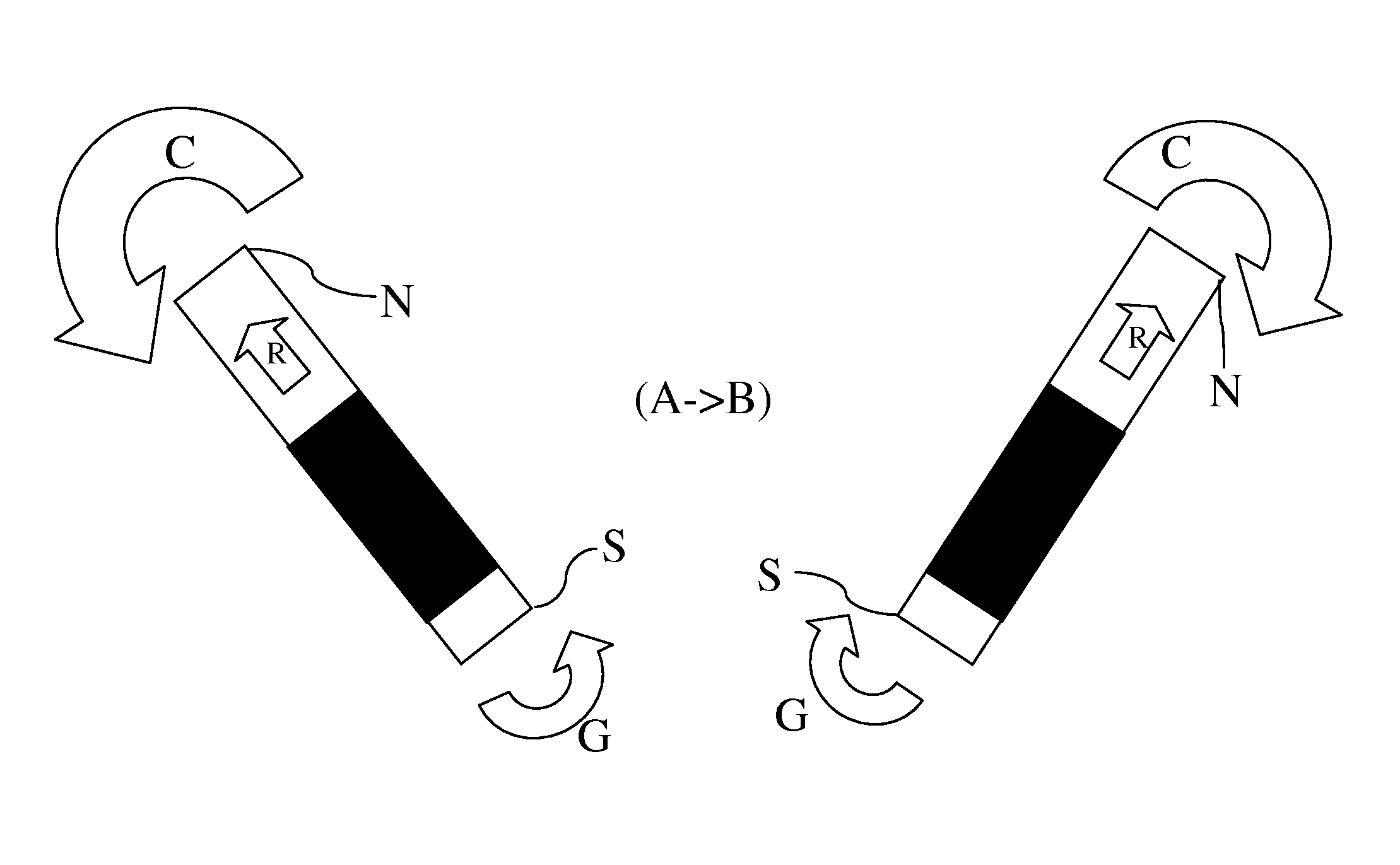
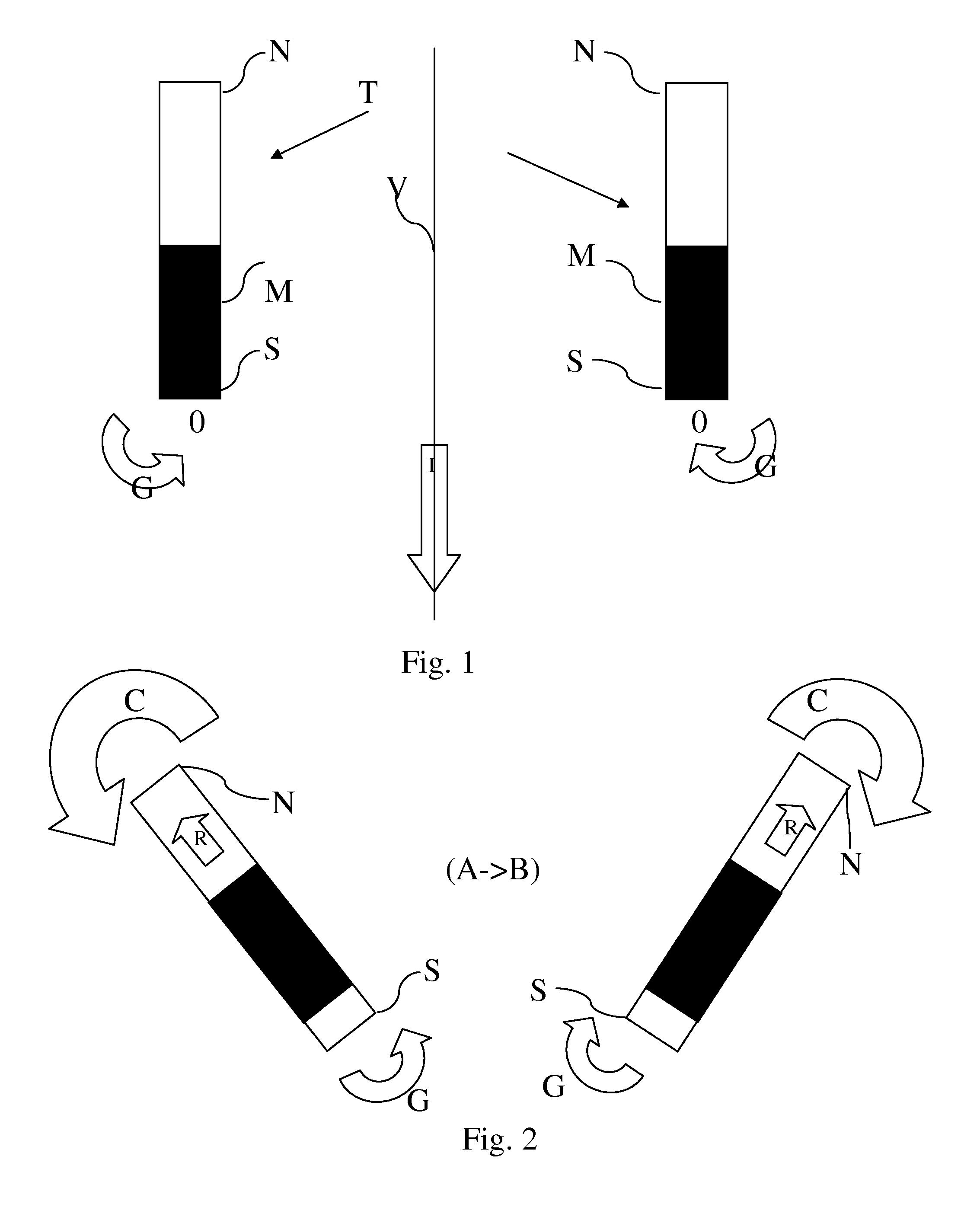
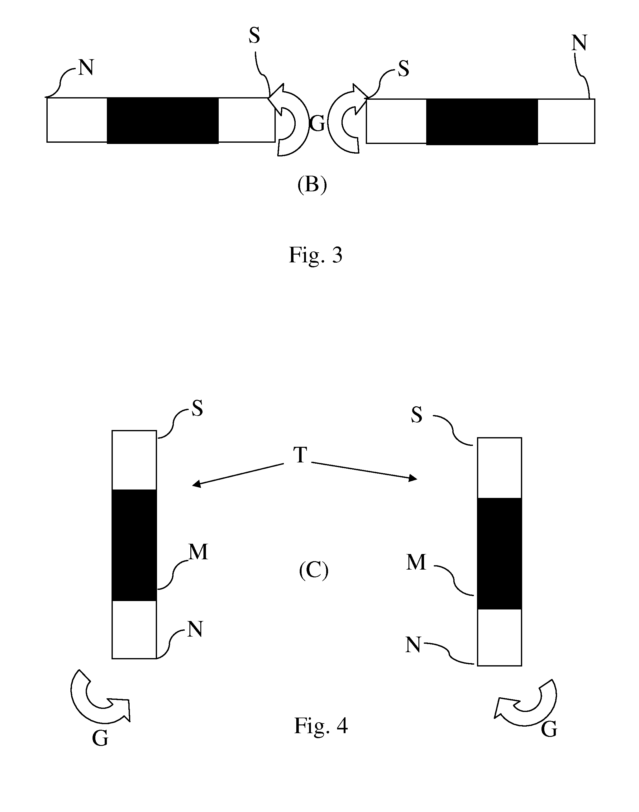
[0027]With reference to the figures, a pair of guides, for example hollow tubular bodies T, are provided, in each one of them a sliding mass W is housed and is able to slide in at least a portion of the tubular body T, whose motion, within the respective tubular body, is controllable. The tubular bodies T are made to rotate with respect to a respective median fulcrum in a respective plane of rotation. Such planes of rotation are parallel with each other and preferably coincide. They rotate in a direction one opposite the other, according to the curved arrows G, having the same angular speed and preferably being in the same step. The fulcra may coincide. They are represented separately for a better understanding of the invention.

[0028]With reference to the diagram of FIG. 1, in the step (A) the masses T, represented by the black filling, are in extracted position in the proximity of the end S of the tubular body T. They generate an impulse towards the way I according to the movement ...


PUM


Abstract

Inertial traction system based on counter-rotating masses (W) with a variable arm between a maximum value and a minimum value and rotating with an angular direction equal and opposed between each other in planes at least parallel between each other, comprising at least a rotor in order to keep the rotation of said pair of masses (W), means for varying said arm, controllable decoupling means between said rotor and said pair of masses (W), first control means in order to control at least said means for varying the arm in order to compose the respective centrifugal and / or Coriolis forces of the respective masses in order to generate impulses according to a movement line (V) so that a number or an intensity of said impulses is prevalent with respect to a single direction (I) of said line (V).

Description

CROSS REFERENCE TO RELATED APPLICATIONS[0001]The present application claims priority to PCT International Application No. PCT / EP2013 / 062357 filed on Jun. 14, 2013, which application claims priority to European Patent Application No. 12171961.1 filed Jun. 14, 2012, the entirety of the disclosures of which are expressly incorporated herein by reference.STATEMENT RE: FEDERALLY SPONSORED RESEARCH / DEVELOPMENT[0002]Not Applicable.APPLICATION FIELD OF THE INVENTION[0003]The present invention relates to the field of impulsive traction systems, wherein impulses are generated to move a body.DESCRIPTION OF THE PRIOR ART[0004]Impulsive movement devices are known which generate impulses along a direction of movement of a body. U.S. Pat. No. 5,156,058 describes a pair of counter-rotating wheels having perimetrally arranged masses which, during the rotation of each wheel, may be moved by increasing or decreasing the eccentricity of the wheels, in order to generate impulsive centrifugal forces whic...

Claims


Application Information

Patent Timeline
IPC IPC(8): F03G3/00
CPCF03G3/00Y10T74/18528
Inventor FALESIEDI, OSVALDO
Owner STC SRL
Why Eureka
Try Eureka