Rotating shaft holding mechanism and rotational viscometer with same

a technology of rotating shaft and rotating shaft, which is applied in the direction of mechanical equipment, sliding contact bearings, instruments, etc., can solve the problems of reducing the resistance of rotation to fluctuation with the rotation of the shaft, and the reduction of the precision of rotating shaft and frictional resistance of rotating sha

Active Publication Date: 2015-06-11
NAT INST OF ADVANCED IND SCI & TECH
View PDF2 Cites 2 Cited by
  • Summary
  • Abstract
  • Description
  • Claims
  • Application Information

AI Technical Summary

Benefits of technology

[0021]A rotating shaft holding mechanism of the present invention makes it possible to achieve a high-precision bearing that is more compactible than a conventional ball bearing or air bearing, that is free of disturbances that would be cause by frictional resistance or a rolling motion of a rotating body in the case of a ball bearing, and that is free of the influence of air pressure that would be exerted in the case of an air bearing.
[0022]Further, the employment of a rotating shaft holding mechanism of the present invention in a bearing of a rotational viscometer makes it possible to achieve a compact, high-precision viscometer.

Problems solved by technology

This reduces the precision of the rotating shaft and the frictional resistance of the rotating shaft.
However, the rotating bodies held in the bearing affect the precision of the rotating shaft and, furthermore, cause the resistance of rotation to fluctuate with the rotation of the shaft.
However, the air bearing has the drawbacks of requiring a high-pressure air source and, what is more, of being not so compactible and being therefore high in moment of rotation.
Further, the pressure of air that is supplied to the air bearing can be a source of generation of torque in some cases, and is a matter that requires attention when the air bearing is used as a bearing for high-precision torque measurement.

Method used


Image

  • Rotating shaft holding mechanism and rotational viscometer with same
  • Rotating shaft holding mechanism and rotational viscometer with same
  • Rotating shaft holding mechanism and rotational viscometer with same

Examples


embodiments

Embodiment 1

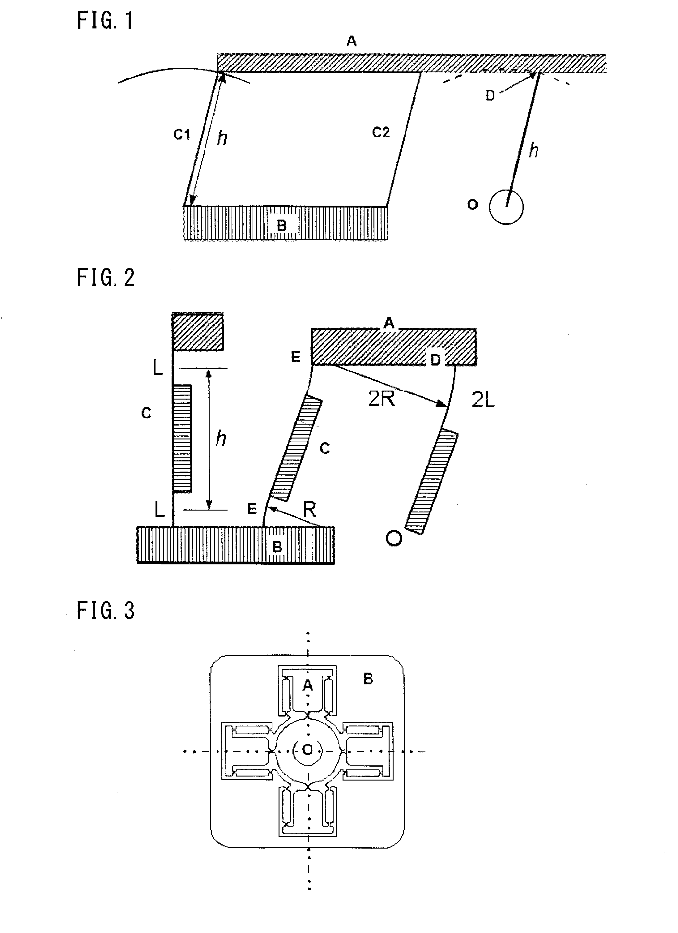
[0040]FIG. 3 is a diagram showing an embodiment of a rotating shaft holding mechanism of the present invention. FIG. 4 is a partially-enlarged view of a main part of the embodiment.

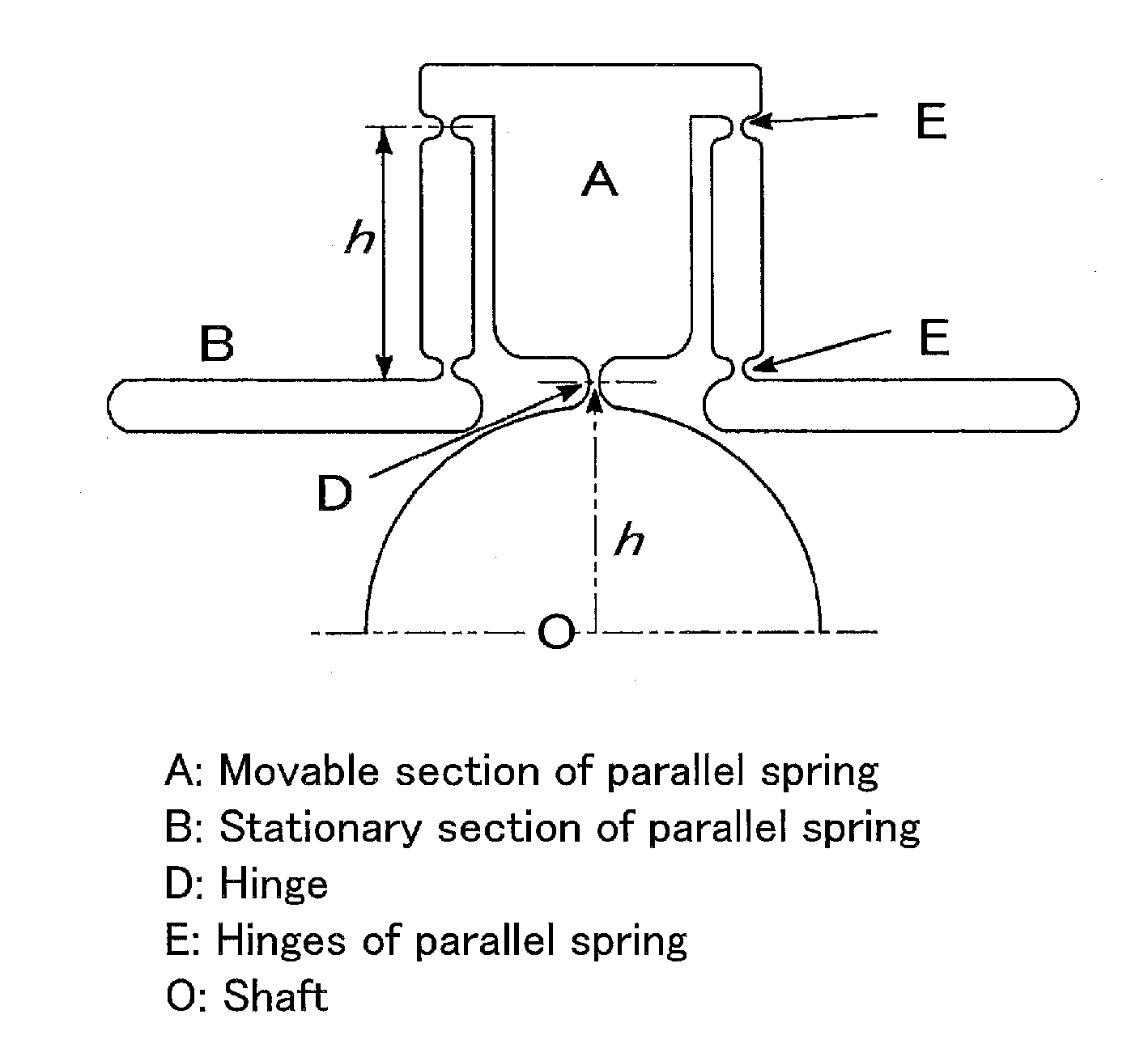
[0041]FIG. 3 shows an example where a rotating shaft holding mechanism of the present invention is achieved by wire-cut processing or the like. In the example shown in FIG. 3, four links each formed by a parallel spring are placed at intervals of 90 degrees. In FIG. 3, A denotes a movable section of each of the parallel springs, B denotes a stationary section of each of the parallel springs, and O denotes a rotating shaft. FIG. 4 is an enlarged view of one of the four parallel spring links shown in FIG. 3. In FIG. 4, A denotes the movable section of the parallel spring, B denotes the stationary section of the parallel spring (drawn in simpler form for convenience of explanation, albeit not coincident in shape with that shown in FIG. 3), D denotes a hinge, E denotes hinges of the parallel sprin...

embodiment 2

[0045]Since a rotating shaft holding mechanism of the present invention has a parallel spring structure, there is theoretically a proportional relationship between the torque and the angle of rotation. Therefore, it can be used in a torque meter by measuring the angle of rotation. Utilizing this makes it possible to serve as a torque measurement unit of a rotational viscometer. Alternatively, it can be used in a torque meter by, when the torque measuring shaft is rotationally displaced, applying, to the torque measuring shaft, torque that cancels out the rotational displacement and calculating the value of the torque applied.

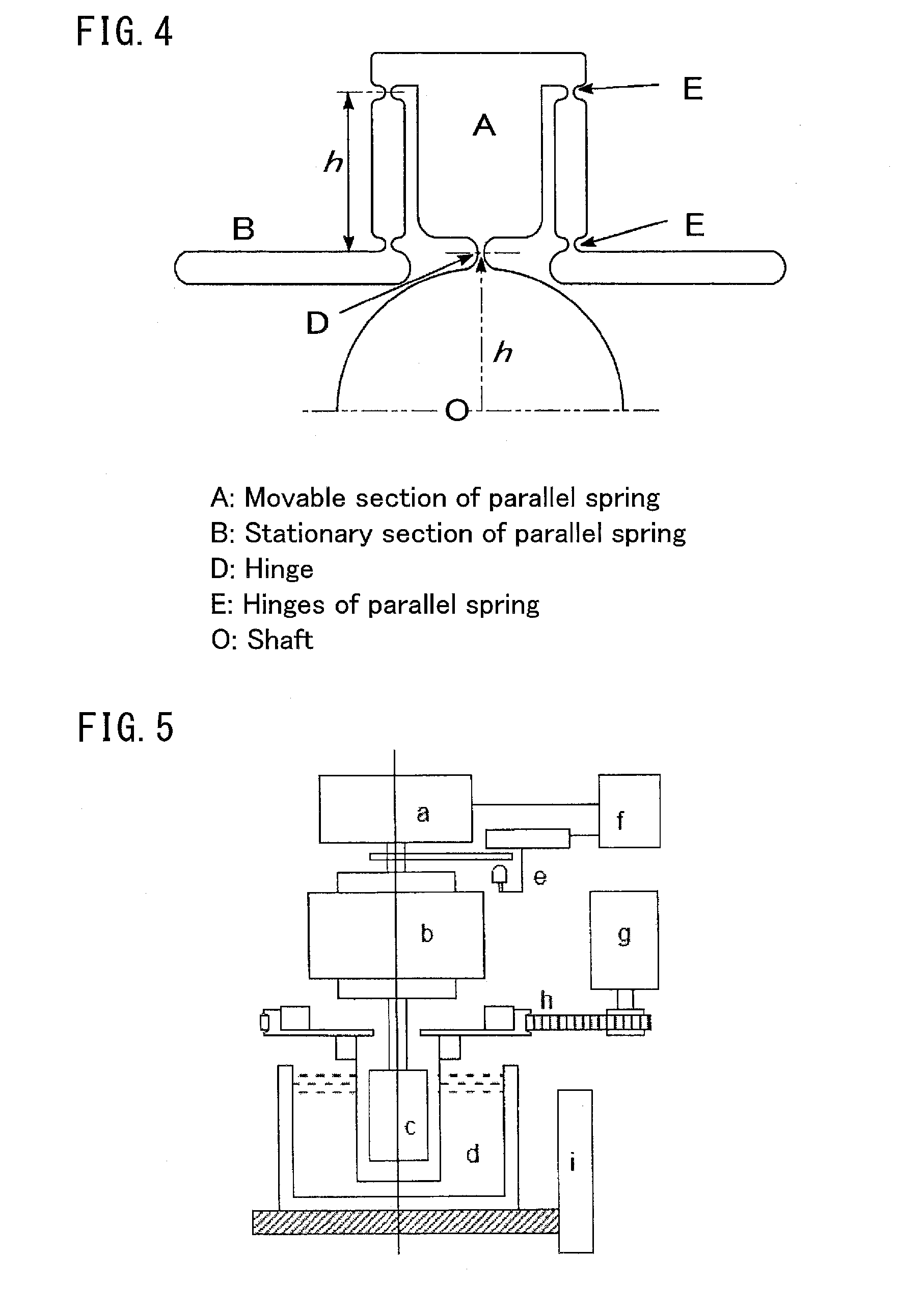
[0046]FIG. 5 shows a conventional rotational viscometer (of a coaxial bicylindrical type). In FIG. 5, a, e, and f denote a torque detection mechanism, b denotes an air bearing, c denotes inner and outer cylinders, d denotes a constant-temperature bath, g and h denote a rotating mechanism of the outer cylinder, and i denotes a raising and lowering mechanism of th...


PUM

PropertyMeasurementUnit
finite anglesaaaaaaaaaa
distanceaaaaaaaaaa
lengthaaaaaaaaaa

Abstract

A compact and high-precision rotating shaft holding mechanism is provided which can be utilized for a device that requires a small amount of rotation.
A rotating shaft holding mechanism includes a plurality of parallel spring links, each of the plurality of parallel spring links including: a movable side connected to a rotating shaft by a hinge at a connection point at a distance h radially away from a center of rotation of the rotating shaft; a plurality of deformable sides which are parallel to each other; hinges each of which connects one end of a corresponding one of the deformable sides to the movable side; and hinges each of which connects the other end of a corresponding one of the deformable sides to the stationary section, the effective length of each of the deformable sides being set to h to permit the rotating shaft, which is connected to the movable side by the hinge at the connecting point at the distance h radially away from the center of rotation of the rotating shaft, to rotate within a range of finite angles, the plurality of parallel spring links including at least two parallel spring links oriented in different directions. A rotational viscometer uses the rotating shaft holding mechanism.

Description

TECHNICAL FIELD[0001]The present invention relates to a rotating shaft holding mechanism that can be utilized for mechanisms and devices, of those which require rotating shafts, which require only small amounts of rotation.[0002]Further, the rotating shaft holding mechanism is the one that was devised to solve the problems in the field where high-precision torque measurement is required. In particular, the rotating shaft holding mechanism is intended to be utilized for torque measurement in a rotational viscometer or a rotational viscometer type rheometer (both of which are hereinafter referred to simply as “rotational viscometer”). Therefore, the present invention relates to a viscometer having a rotating shaft holding mechanism.BACKGROUND ART[0003]Conventionally, for many a rotating shaft, a structure such as a ball bearing in which rotating bodies are held have been used. This reduces the precision of the rotating shaft and the frictional resistance of the rotating shaft. However...

Claims


Application Information

Patent Timeline
Patent Type & Authority Applications(United States)
IPC IPC(8): F16C27/02G01N11/14
CPCG01N11/14F16C27/02F16C2370/00F16C11/12F16C11/00F16C11/04G01L3/00F16C1/02
Inventor NASHIMA, TAKESHIYAMAMOTO, YASUYUKI
Owner NAT INST OF ADVANCED IND SCI & TECH
Why Eureka
Try Eureka