Viscometer

a viscosity and metering technology, applied in the field of viscometers, can solve the problems of loss of print quality and possible blockage of the head, additional downtime, costs and potential errors, and slow response to changes in the viscosity of the ink in the tank, and achieve the effect of measuring the viscosity

Inactive Publication Date: 2015-06-11
VIDEOJET TECH INC
View PDF9 Cites 23 Cited by
  • Summary
  • Abstract
  • Description
  • Claims
  • Application Information

AI Technical Summary

Benefits of technology

[0009]In one aspect, a viscometer includes a housing and a bob disposed in the housing such that a gap is provided between the bob and the housing. The bob includes a magnet. A linear support supports the bob such that the bob is free to rotate with respect the housing. A flow inlet in the housing provides fluid flow into the housing. A flow outlet pr

Problems solved by technology

As the ink circulates through the system, there is a tendency for it to thicken as a result of solvent evaporation.
Solvent is lost through evaporation; over time, this leads to an increase in the viscosity of the ink which will lead to a loss of print quality and possible blocking of the h

Method used


Image

  • Viscometer
  • Viscometer
  • Viscometer

Examples


example

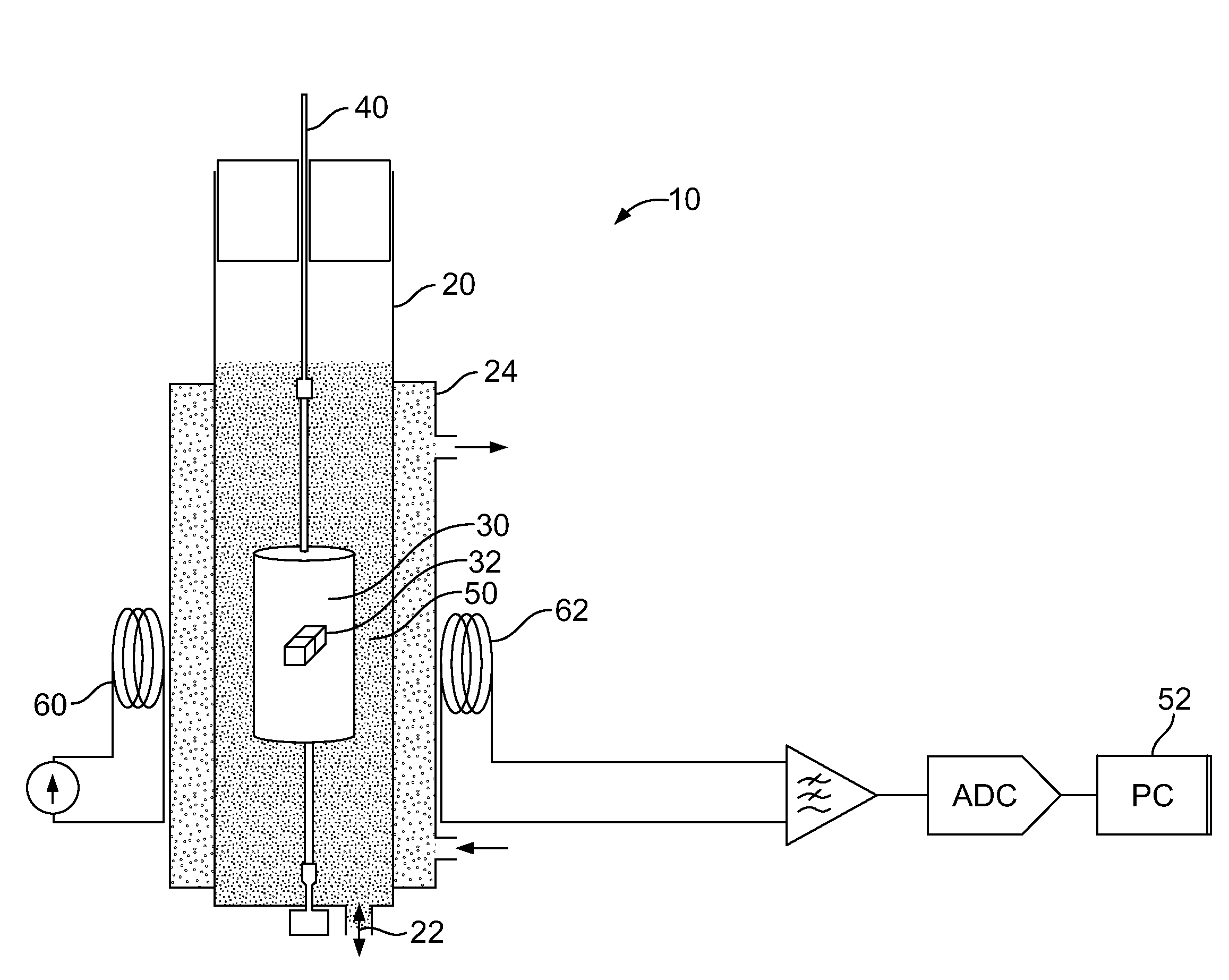
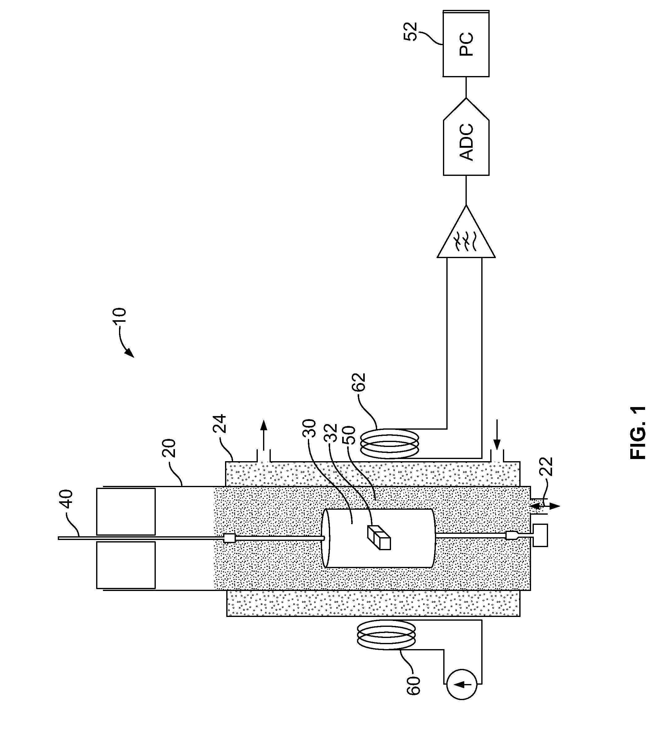
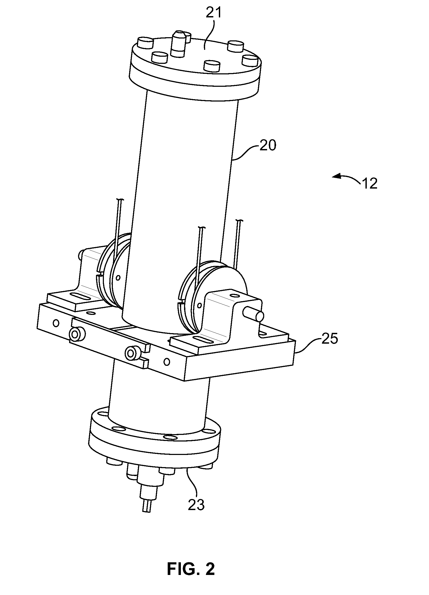
[0038]The motion of the bob of the viscometer of FIGS. 2-4 follows the equations:

θ(t)=θ0-γtcos(ω0t)(1)γ=A·ω0ηρ(2)A=πr3L2M(3)

where

[0039]θ=angular displacement of bob

[0040]γ=damping constant

[0041]ω0=2πf0=oscillation frequency

[0042]η=viscosity

[0043]ρ=fluid density

[0044]r=bob radius

[0045]L=bob length

[0046]M=bob moment of inertia

[0047]The system measures the angular position of the bob as a function of time, as shown in FIG. 5. The angular amplitude can be determined from this data, as shown in FIG. 6. The viscosity of a fluid can determined by fitting angular displacement data to an equation of the form

√{square root over (ηf0ρ)}=Kγ+C  (4)

where K and C are constants determined by calibrating the system.

[0048]To measure the viscosity we need to know the value of ρ, and determine the values of f0 (or ω0) and γ by measuring the motion of the bob. Two different methods can be used determine γ as described below. In this example, the fluid used was water.

[0049]In a first Method, γ is calculat...


PUM


Abstract

A viscometer includes a housing and a bob disposed in the housing such that a gap is provided between the bob and the housing. The bob includes a magnet. A linear support supports the bob such that the bob is free to rotate with respect the housing. A flow inlet in the housing provides fluid flow into the housing. A flow outlet provides fluid flow out of the housing. At least one coil is disposed adjacent the housing for providing a magnetic field to induce oscillating rotational movement in the bob and to measure the movement of the bob. The viscometer is configured to measure a viscosity of a fluid by inducing movement in the bob and measuring a dampening effect of the fluid.

Description

BACKGROUND[0001]The present disclosure relates to a viscometer for measuring the viscosity of a fluid. It is particularly useful for measuring the viscosity of ink in an ink jet printer.[0002]In ink jet printing systems the print is made up of individual droplets of ink generated at a nozzle and propelled towards a substrate. There are two principal systems: drop on demand where ink droplets for printing are generated as and when required; and continuous ink jet printing in which droplets are continuously produced and only selected ones are directed towards the substrate, the others being recirculated to an ink supply.[0003]Continuous ink jet printers supply pressurized ink to a print head assembly having a drop generator where a continuous stream of ink emanating from a nozzle is broken up into individual regular drops by an oscillating piezoelectric element. The drops are directed past a charge electrode where they are selectively and separately given a predetermined charge before...

Claims


Application Information

Patent Timeline
IPC IPC(8): G01N11/16
CPCG01N11/162B41J2/175B41J2/17513B41J2/195G01N11/14G01N11/16G01N2011/0046G01N2011/0086
Inventor LEWIS, EMMAJORDAN, SIMONSTAMP, MICHAELLAWSON, SIMON MARK
Owner VIDEOJET TECH INC
Why Eureka
Try Eureka