
MEMS-microviscometer

a microviscometer and micro-scopy technology, applied in the field of micro-scopy devices, can solve problems such as inability to accurately measure capacitive distances, and achieve the effects of high viscosity, convenient small design, and easy to measure viscosity

Active Publication Date: 2017-05-02
IHP GMBH INNOVATIONS FOR HIGH PERFORMANCE MICROELECTRONICS LEIBNIZ INST FUR INNOVATIVE
View PDF20 Cites 1 Cited by
  • Summary
  • Abstract
  • Description
  • Claims
  • Application Information

AI Technical Summary

Benefits of technology

The invention is a MEMS device that uses RF voltage to move an actuator and detect an impedance change through a viscous fluid. This RF voltage source is also used to generate the measurement signal, eliminating the need for a separate device to drive the actuator. This small design allows for continuous monitoring and individualized adjustment of drug delivery, as well as permanent implantation for blood-sugar monitoring. A lock detector or frequency detector is used to compare the frequencies of reference and measurement oscillators and generate a switch-off signal to ensure accurate measurements.

Problems solved by technology

In a conductive fluid, e.g. in an isotonic saline solution, this form of electrostatic drive cannot be used because the electrodes become polarized within fractions of microseconds, which reduces or eliminates the E-field in the fluid that is required for the drive, or additionally at higher voltages, electrolysis starts, releasing hydrogen.
Using a DC voltage or a low-frequency voltage is not only unsuitable for the actuator drive in a conductive fluid but also, owing to an ion current and polarization effects on the electrodes, will result in an incorrect capacitive distance measurement, for example.

Method used


Image

  • MEMS-microviscometer
  • MEMS-microviscometer
  • MEMS-microviscometer

Examples


Embodiment Construction

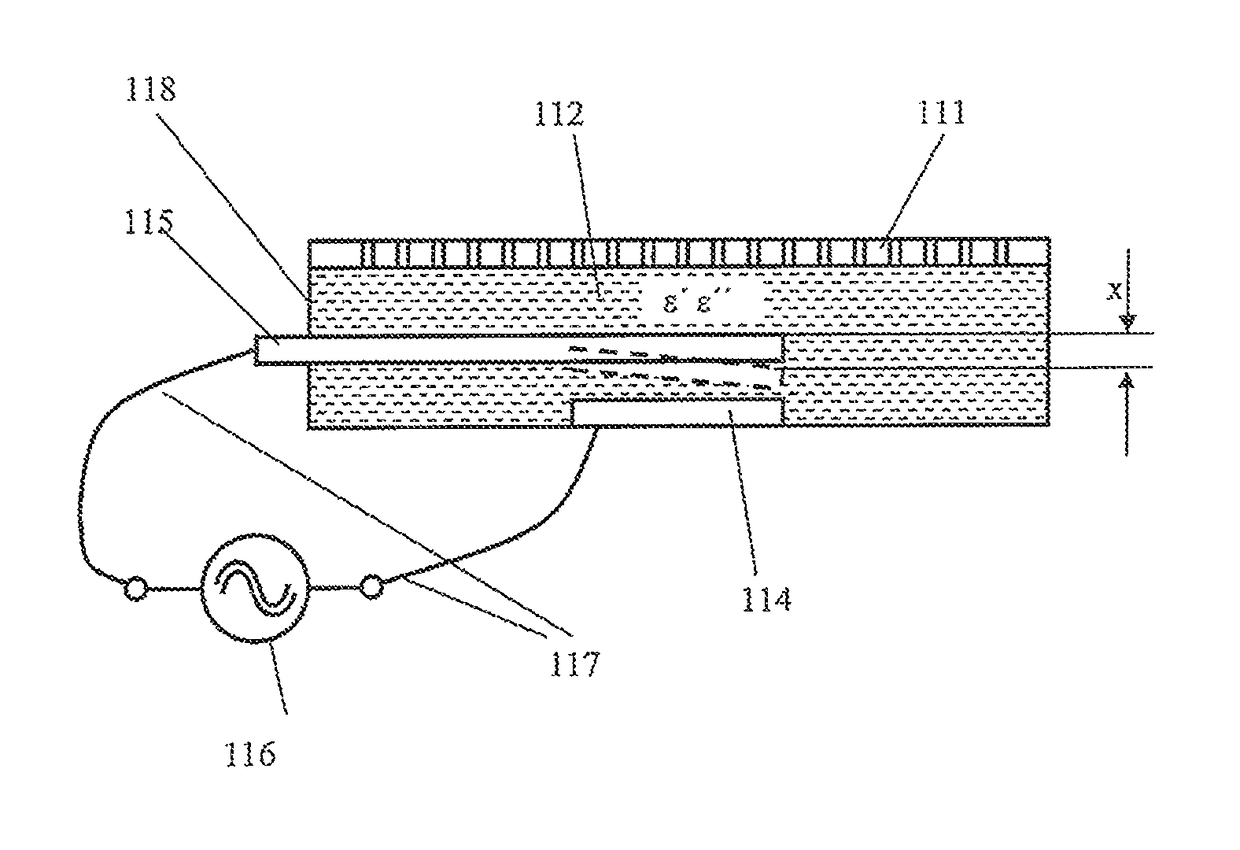
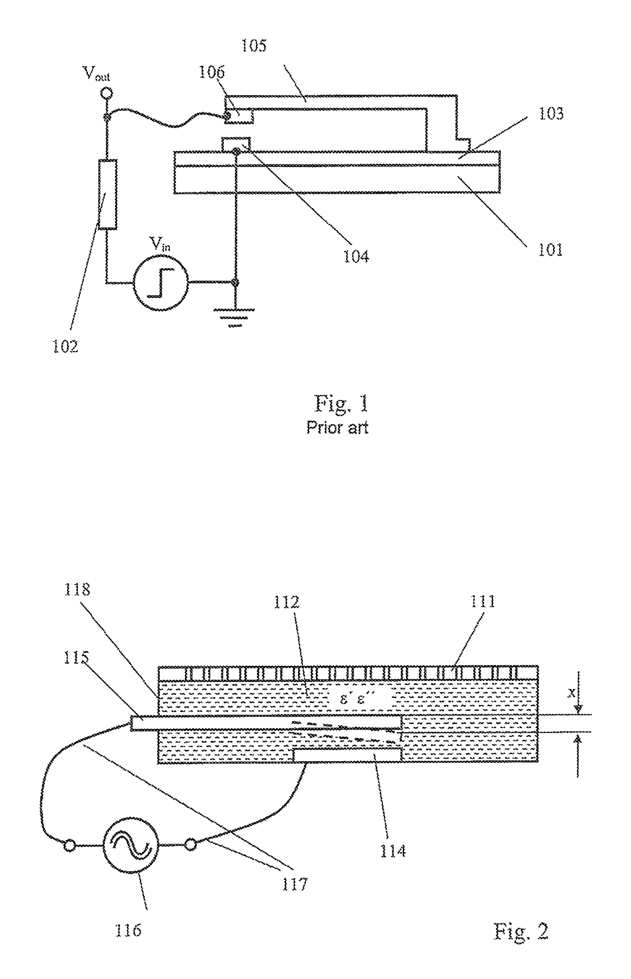
[0059]For the purpose of explaining an exemplary embodiment described below, FIG. 2 shows a schematic cross-sectional view of a measuring chamber 118 of a MEMS micro-viscometer. When an RF voltage is applied between an actuator in the form of an elastically deformable cantilever 115 and the counter electrode thereto, a ground electrode 114, a voltage is dropped between the electrode of the cantilever 115 and the ground electrode 114 across the fluid to be measured (measuring fluid) 111. As a result of the force of attraction between the electrodes, the cantilever 115 moves at a viscosity-dependent speed towards the counter electrode until the RF voltage is switched off by a measuring device which evaluates the frequency, an amplitude or a phase of the RF voltage.

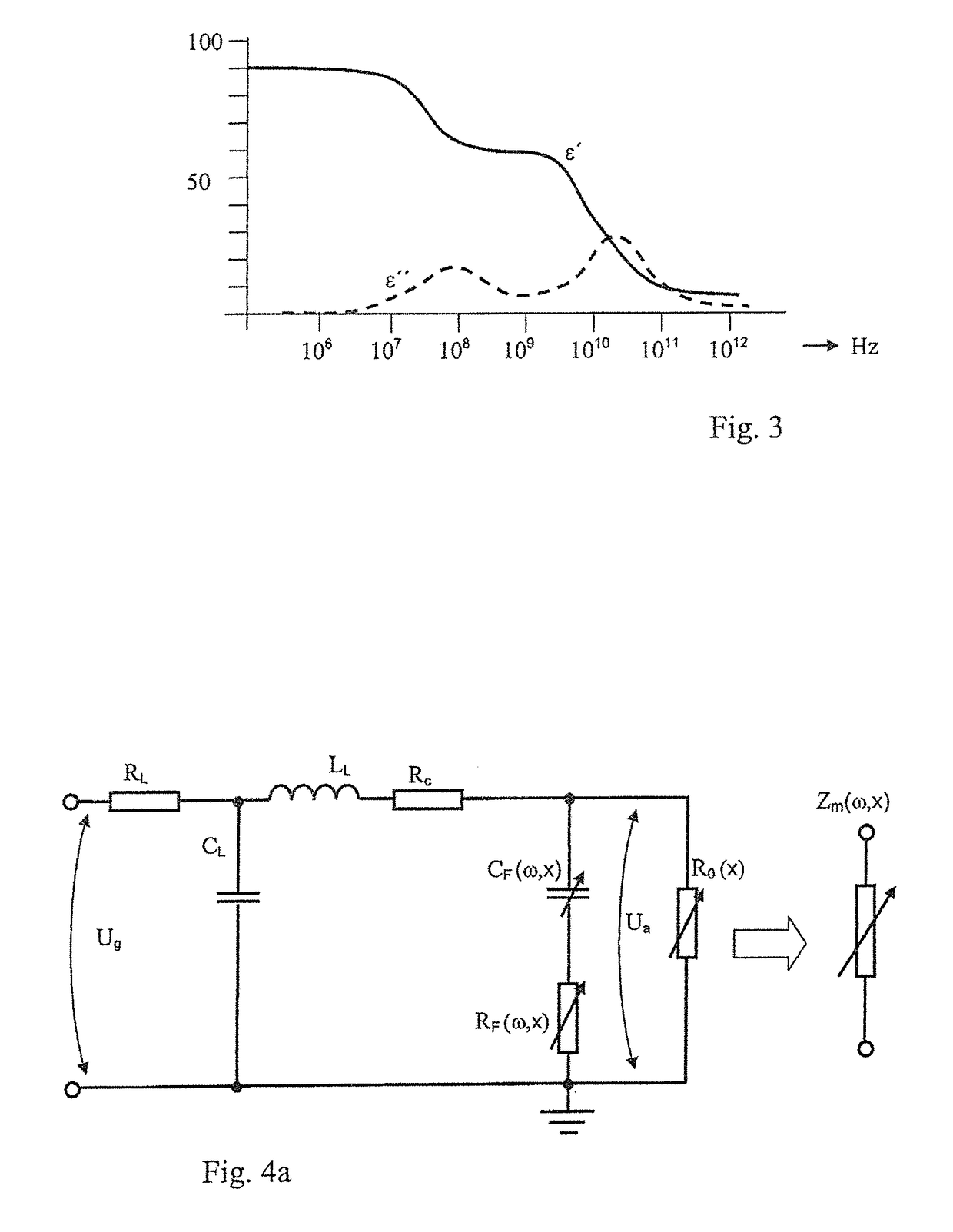
[0060]The electrical properties of the fluid must not be ignored even when using an RF voltage to drive the actuator. The alternating current flowing through the fluid loads the RF voltage source according to the deflection ...


PUM

PropertyMeasurementUnit
frequencyaaaaaaaaaa
frequencyaaaaaaaaaa
frequencyaaaaaaaaaa

Abstract

Micro-electromechanical device for measuring the viscosity of a fluid, comprises a measuring chamber with a micromechanical actuator, arranged as a cantilever above a metallically conductive counter electrode, elastically deformable towards the counter electrode, surrounded by the fluid to be measured and made of a metallically conductive material, a two-terminal RF voltage source that can be switched off, having a first output terminal connected to the actuator, and a second output terminal connected to the counter electrode, and which is designed to output an RF voltage signal that is suitable for deflecting the actuator out of its rest position, and a measuring device to detect a change in the frequency, amplitude or phase of the RF signal in order to determine a measurement value for the viscosity-dependent speed at which the actuator is deformed.

Description

CROSS REFERENCE TO RELATED APPLICATIONS[0001]This application claims priority under 35 USC §119 to German Patent Application No. 10 2012 210 470.4 filed on Jun. 21, 2012, which application is hereby incorporated by reference in its entirety.TECHNICAL FIELD[0002]The invention relates to a MEMS device and a method for measuring the viscosity of extremely small fluid volumes using a micro-viscometer.BACKGROUND OF THE INVENTION[0003]Micro-viscometers of this type are used, inter alia, in affinity viscometry for determining the glucose content of an analyte, for example of blood. For this purpose, a separating membrane that allows a selective exchange of molecules is arranged between analyte and a measuring fluid, whereby the viscosity of the measuring fluid is directly related to the glucose content of the analyte.[0004]The operating principle of the measuring fluid is based, for example, on the exchange of dextran molecules occupying the sugar-binding sites of a lectin molecule with gl...

Claims


Application Information

Patent Timeline
Patent Type & Authority Patents(United States)
IPC IPC(8): G01N11/00G01N11/16
CPCG01N11/00G01N11/16
Inventor BIRKHOLZ, MARIODREWS, JURGENEHWALD, KARL-ERNSTGENSCHOW, DIETERHAAK, ULRICHKULSE, PHILIPMATTHUS, EGBERTSCHULZ, KATRINWINKLER, WOLFGANGWOLANSKY, DIRKFROHLICH, MARLEN
Owner IHP GMBH INNOVATIONS FOR HIGH PERFORMANCE MICROELECTRONICS LEIBNIZ INST FUR INNOVATIVE
Learn More