Method and Apparatus for Reducing Noise in a Coded Aperture Radar

a coded aperture radar and noise reduction technology, applied in the field of coding for use with coded aperture radars, can solve the problems of reducing increasing the computational overhead of the type i car system, and limiting the sensitivity of the car compared to the conventional, so as to reduce the sensitivity and dynamic range of the radar

Active Publication Date: 2015-06-11
HRL LAB
View PDF2 Cites 18 Cited by
  • Summary
  • Abstract
  • Description
  • Claims
  • Application Information

AI Technical Summary

Benefits of technology

[0009]Type I CAR provides a method and apparatus for acquiring information about the 3D location and radial velocity of a continuum of scatterers within a relatively short acquisition period compared to conventional radar as mentioned above. The Type I CAR technique has been previously made the subject of patent applications (see the US patent applications identified above), along with suggestions for coding the single bit phase shifters located at each aperture transmitting and / or receiving element. However, the previously disclosed techniques produce a uniformly distributed ambiguity, sometimes called residual ambiguity or multiplicative noise, which reduces the sensitivity and dynamic range of the radar.

Problems solved by technology

Sensitivity is often limited in CAR compared to a conventional phased array radar because energy is typically collected in a relatively short period of time, consisting of a single radar range / Doppler acquisition when using CAR.
However, in that case the number of Doppler bins increases a factor of N, increasing the computational overhead of the Type I CAR system.
However, the previously disclosed techniques produce a uniformly distributed ambiguity, sometimes called residual ambiguity or multiplicative noise, which reduces the sensitivity and dynamic range of the radar.

Method used


Image

  • Method and Apparatus for Reducing Noise in a Coded Aperture Radar
  • Method and Apparatus for Reducing Noise in a Coded Aperture Radar
  • Method and Apparatus for Reducing Noise in a Coded Aperture Radar

Examples


Embodiment Construction

[0024]The technique described herein utilizes additional measurements made in a time period that is constrained by range and velocity discretization. As a result this technique requires a faster analog to digital converter (ADC) than the techniques used in the US patent applications referenced above. But an advantage compared to the US patent applications referenced above is that the residual ambiguity is lower than the previous applications.

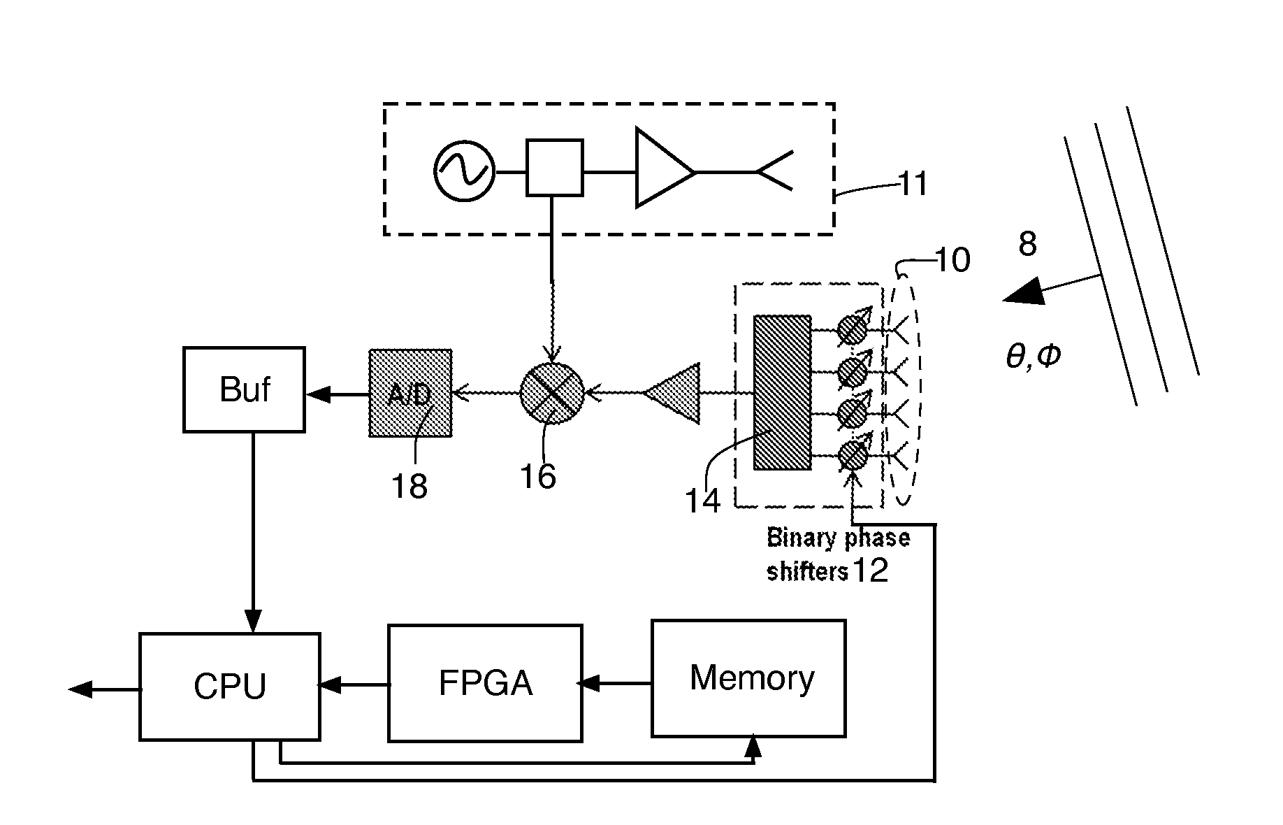
[0025]FIG. 1 shows a block diagram of a CAR coded radar, with CAR coding being employed, for simplicity's sake, only on the receive portion of the radar. The possibility of using CAR on the transmitted signal as well is discussed towards the end of this patent. The radar is much simpler to design (and is much less complicated to implement, and thus less computationally expensive) if the CAR coding disclosed herein is employed at the only receiver side of the radar. As such, the receive only embodiments disclosed herein are preferred for a low co...


PUM


Abstract

A method and apparatus for reducing noise in a coded aperture radar system, the coded aperture radar system transmitting signals which occur in sweeps, with K sweeps utilized to cover field of view of the coded aperture radar system and Q frequency shifts or steps occurring each sweep thereof. An array of N antenna elements is provided, the array of antenna elements each having an associated two state modulator coupled therewith. Energy received at the array is modulated according to a sequence of multibit codes, the number of codes in the sequence of codes comprising at least K times Q times N, thereby reducing noise in the coded aperture radar system compared to a coded aperture radar system radar system having fewer than K times Q times N codes in its sequence of multibit codes.

Description

CROSS REFERENCE TO RELATED APPLICATIONS[0001]This application claims priority to and the benefit of U.S. Provisional Patent Application Ser. No. 61 / 912,990, filed Dec. 6, 2013 and entitled “A Method and Apparatus for Processing Coded Aperture Radar Signals” and U.S. patent application Ser. No. 14 / 561,111 filed on the same date as this application and entitled “A Method and Apparatus for Processing Coded Aperture Radar Signals” (Attorney Docket 629073). The disclosure of that U.S. Provisional Patent Application Ser. No. 61 / 912,990 and the U.S. patent application Ser. No. 14 / 561,111 identified above are hereby incorporated herein by this reference in their entirety.[0002]This application is related to U.S. patent application Ser. No. 13 / 490,607 filed Jun. 7, 2012 and entitled “Coded Aperture Beam Analysis Method and Apparatus”, the disclosure of which is hereby incorporated herein by reference.[0003]This application is also related to U.S. patent application Ser. No. 13 / 725,621 filed ...

Claims


Application Information

Patent Timeline
Patent Type & Authority Applications(United States)
IPC IPC(8): G01S7/28G01S13/34G01S13/58G01S13/931G01S13/935
CPCG01S7/2813G01S13/34G01S13/588G01S13/343G01S13/4418G01S13/4463G01S13/536G01S13/882G01S13/931G01S13/935G01S7/356G01S7/02G01S13/02
Inventor LYNCH, JONATHAN J.
Owner HRL LAB
Why Eureka
Try Eureka