
Gas Turbine Engine for Long Range Aircraft

Active Publication Date: 2015-06-18
RAYTHEON TECH CORP
View PDF1 Cites 2 Cited by
  • Summary
  • Abstract
  • Description
  • Claims
  • Application Information

AI Technical Summary

Benefits of technology

The gas turbine engine described in this patent has several technical features. First, it has a high overall pressure ratio, meaning the air pressure at the compressor rotors is very high. Second, it has a high bypass ratio, meaning the amount of air delivered as bypass flow compared to the amount of air delivered into the core housing is very high. Third, the fan drive turbine has multiple stages, meaning it has multiple parts that work together to drive the compressor rotors. Fourth, the gear ratio of the gear reduction is high, meaning the gear ratio is greater than or equal to about 2.6. Fifth, there may be additional turbine rotors upstream of the fan drive turbine. These technical features make the gas turbine engine more efficient, reliable, and suitable for long range aircraft.

Problems solved by technology

However, there has been a significant limitation in that the stress and temperature at the downstream end of the downstream compressor rotor limits how high the overall compression ratio may reach.

Method used


Image

  • Gas Turbine Engine for Long Range Aircraft
  • Gas Turbine Engine for Long Range Aircraft

Examples


Embodiment Construction

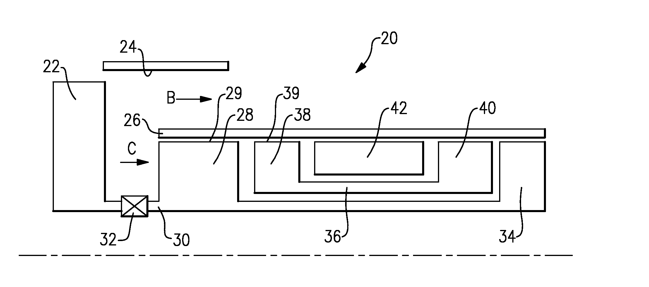
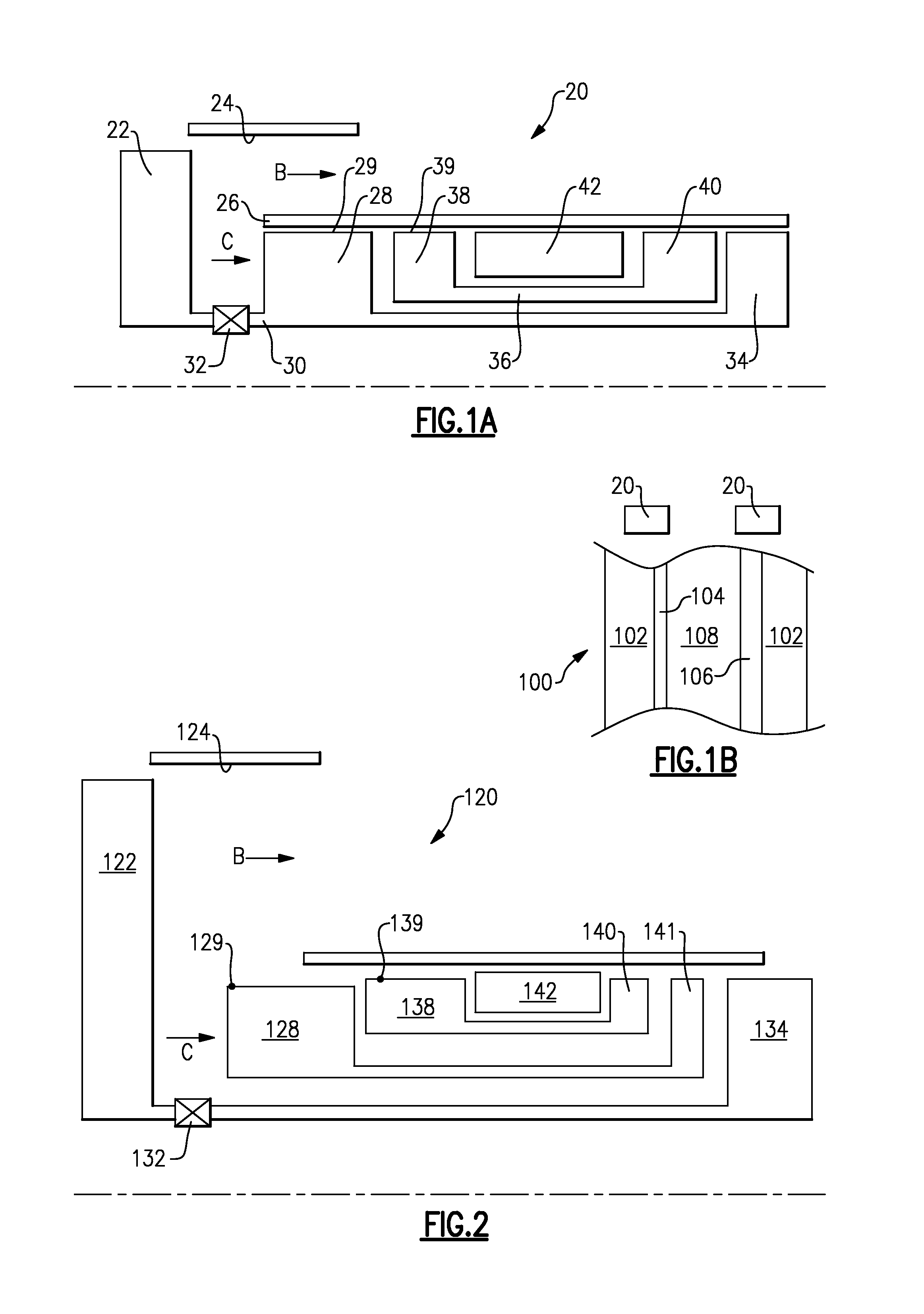
[0033]A gas turbine engine 20 shown schematically in FIG. 1A, is designed for use on long range aircraft.

[0034]As known, a fan rotor 22 delivers bypass air B within a nacelle 24. A core engine housing 26 receives core air flow C from the fan rotor 22. The core air flow C initially reaches an upstream compressor rotor 28, which compresses the air to a first lower level and then delivers that air into a downstream compressor rotor 38, where additional compression occurs.

[0035]The air from the compressor rotor 38 is delivered into a combustion section 42, mixed with fuel and ignited. Products of this combustion pass downstream over an upstream turbine rotor 40, which operates at a higher pressure and speed and drives a shaft 36 to drive the downstream compressor rotor 38. Downstream of the turbine rotor 40, the products of combustion drive a fan drive turbine 34 which is a downstream turbine rotor and operates at a lower pressure and speed than does the turbine rotor 40. The fan drive ...


PUM


Abstract

A gas turbine engine comprises a fan for delivering air into a bypass duct as bypass flow, into a core housing as core flow, with the core housing containing an upstream compressor rotor and a downstream compressor rotor. An overall pressure ratio is defined across the upstream and downstream compressor rotors. A bypass ratio is defined as a volume of air delivered as bypass flow compared to a volume of air delivered into the core housing. The overall pressure ratio is greater than or equal to about 45.0, and the bypass ratio is greater than or equal to about 11.0.

Description

BACKGROUND OF THE INVENTION[0001]This application relates to a gas turbine engine designed for use on longer range aircraft.[0002]Gas turbine engines are known and may include a fan delivering air into a bypass duct as propulsion air. In addition, the fan typically delivers air into a core housing and to a compressor. There are, typically, at least two compressor rotors with an upstream or lower pressure rotor compressing the air and then delivering it into a downstream or higher pressure rotor. The compressed air from the downstream compressor rotor is typically delivered into a combustion section where it is mixed with fuel and ignited. Products of this combustion may pass downstream over turbine rotors including an upstream turbine rotor that drives the downstream compressor rotor and a downstream turbine rotor that drives the upstream compressor rotor.[0003]In one type engine, the downstream turbine rotor also drove a fan rotor, such that the fan rotor, the upstream compressor r...

Claims


Application Information

Patent Timeline
IPC IPC(8): F04D19/00
CPCF04D19/002F02C7/36F02K3/06F05D2250/30F05D2260/40311
Inventor SCHWARZ, FREDERICK M.SUCIU, GABRIEL L.
Owner RAYTHEON TECH CORP
Features
  • Generate Ideas
  • Intellectual Property
  • Life Sciences
  • Materials
  • Tech Scout
  • Unparalleled Data Quality
  • Higher Quality Content
  • 60% Fewer Hallucinations
Learn More