LED wall pack

Inactive Publication Date: 2015-06-18
SHENZHEN YAORONG TECH
View PDF38 Cites 27 Cited by
  • Summary
  • Abstract
  • Description
  • Claims
  • Application Information

AI Technical Summary

Benefits of technology

[0014]Preferably, silicone is coated on the area between the

Problems solved by technology

The traditional wall pack which uses general light bulb and incandescent bulb is not as energy-saving or durable as LED light.
Not only do they have low luminous efficiency, hig

Method used


Image

  • LED wall pack
  • LED wall pack
  • LED wall pack

Examples


Embodiment Construction

[0028]To better understand this invention, detailed description of the present invention are set forth below in conjunction with the accompany drawings.

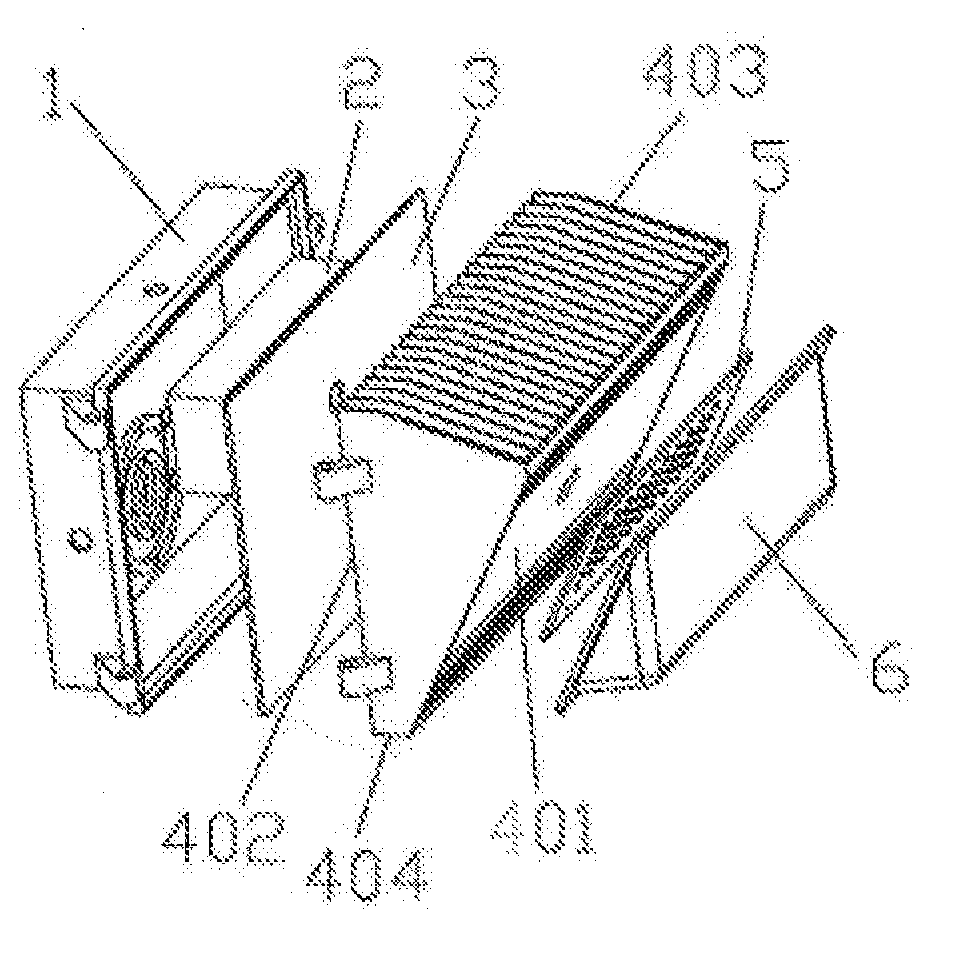
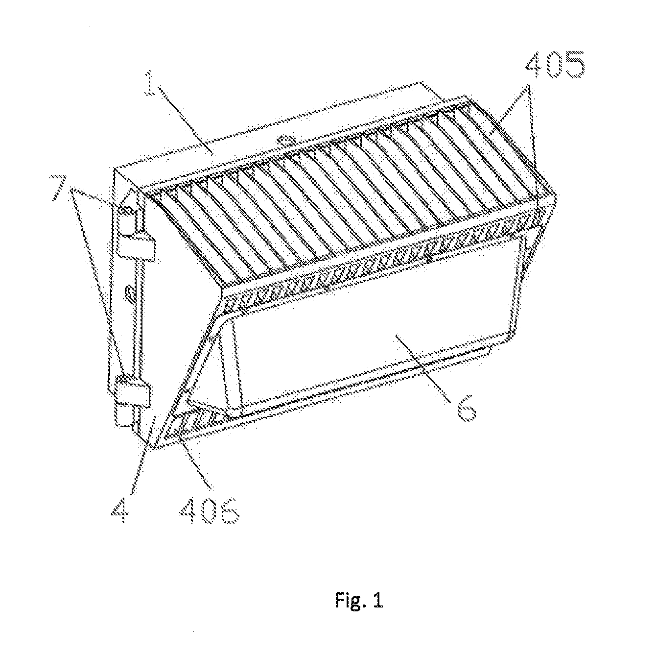
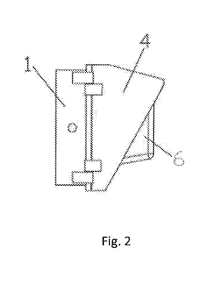
[0029]Referring to FIG. 1, FIG. 2, FIG. 3 and FIG. 4, the present invention of an LED wall pack is disclosed, which mainly comprises a power supply box 1, a power supply 2, a door 3, a heat sink 4, an LED light panel 5, a transparent or translucent protective case 6. The power supply 2 is secured inside the power supply box 1, whereas the power supply box 1 is covered by the door 3. The LED light panel 5 is electrically connected to the power supply 2 and is fixed on the front side of heat sink 401. The protective case 6 is covered on the LED light panel 5 and is secured on the front side 401 of the heat sink 4. The door 3 is fixed on the rear side 402 of the heat sink 4 and the heat sink 4 is connected with the power supply box 1.

[0030]To facilitate airflow, accelerate heat dissipation, and avoid accumulation of dusts, the heat sink...


PUM

PropertyMeasurementUnit
Areaaaaaaaaaaa
Transparencyaaaaaaaaaa
Heataaaaaaaaaa

Abstract

This invention discloses an LED wall pack, which comprises a power supply box; a power supply disposed in the power supply box; a door covered on the power supply box; wherein the LED wall pack also comprises a heat sink, an LED light panel, and a transparent or translucent protective case; in which the LED light panel is connected to the power supply and secured to the front side of the health sink; the protective case is covered on the LED light panel and is secured to the front side of the heat sink; the door is secured on the back side of the heat sink; and the heat sink is connected with the power supply box. The LED wall pack of the invention has good heat dissipation, provides uniform light, enables easy maintenance, and provides long usage life. It can be widely used in the field of lighting.

Description

TECHNICAL FIELD OF THE INVENTION[0001]The present invention generally relates to the field of LED lighting apparatus, and more particularly, to an LED wall pack.BACKGROUND OF THE INVENTION[0002]The traditional wall pack which uses general light bulb and incandescent bulb is not as energy-saving or durable as LED light. Not only do they have low luminous efficiency, high energy consumption and short usage life, they are also affected by poor sealing and uneven light. As the seal design was not used, heat dissipation is therefore not considered.SUMMARY OF THE INVENTION[0003]In response to the aforementioned shortcomings, this invention aims at providing an LED wall pack with good cooling effects and uniform light, which can solve the problems of the absence of cooling design, uneven illumination, low energy efficiency, and short life of the existing wall pack.[0004]To solve the aforementioned technical problems, this invention is implemented through the following technical solutions:[...

Claims


Application Information

Patent Timeline
IPC IPC(8): F21V15/01F21V23/02F21V29/83F21S8/00F21V5/00
CPCF21V15/01F21S8/036F21Y2101/02F21V29/83F21V23/023F21S8/037F21V3/02F21V3/061F21V3/062F21V5/045F21V17/107F21V29/507F21V29/70F21Y2105/10F21Y2115/10
Inventor YONG, XING CHUN
Owner SHENZHEN YAORONG TECH
Why Eureka
Try Eureka